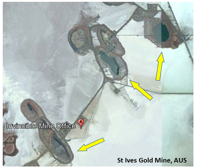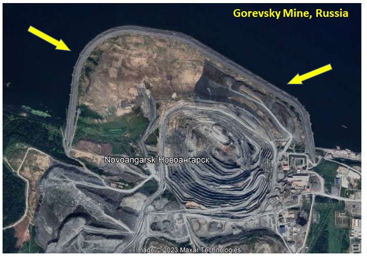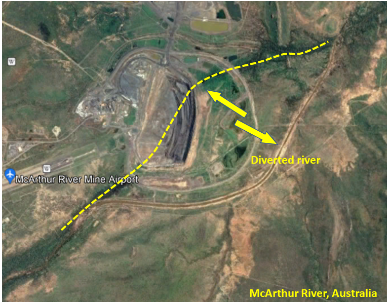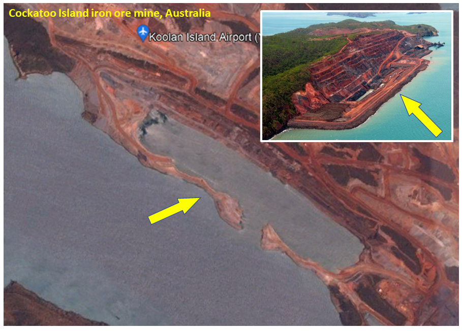
 There have been fairly recent heap leach pad failures in both the Yukon and Turkey and tailings dam failures in Chile and the Philippines. As a result I have been seeing more posts on LinkedIn about the application of satellite based InSAR deformation monitoring. I had never heard of InSAR before, so thought a little bit of background research on my part might be worthwhile. (Note: this article was written in 2024 and technological improvements are happening all the time).
The following are my comments on what InSAR is and where it may be going. I am by no means an expert in this technology and merely viewing it from the perspective of a mining engineer.
What is InSAR
InSAR is satellite-based “Interferometric Synthetic Aperture Radar”. It can measure the distance from a satellite to a ground feature. With repeated imaging it is able to detect changes in distance and hence measure displacements to within 5-10 millimetre accuracy. It can be used as a potentially cost-effective slope monitoring tool, albeit it cannot be the only tool, as is discussed later.
The relevant satellite images have been around for years. Now the availability of analytical software to interpret the satellite data is improving. The technology can detect millimeter-scale displacements, however only in the line-of-sight (LOS) direction of the satellite. Using two or more satellites in different orbits and directions, displacements in horizontal and vertical directions can be evaluated.
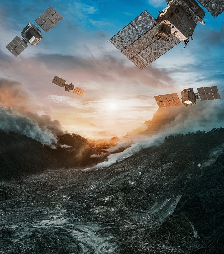
 An example of a satellite being used is the Sentinel-1, launched in mid-2015 by the European Space Agency. This satellite information is open-source data. It will have a 6 to 12 day revisit cycle in many locations.
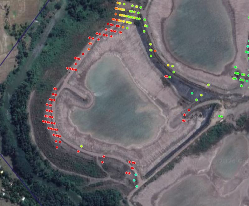
The results of an InSAR displacement survey are typically shown as a series of colored data points, typically coloured green for the stable points, trending to yellow and red for points that are moving.
This blog has some example images.
Some Limitations With InSAR
There are some limitations with InSAR, so it can only be part of a monitoring program. These limitations are:
-
The displacement direction is only measured in the direction of the satellite. Hence one may not always know in which direction the movement is occurring. The magnitude of displacement could be underestimated depending on the apparent angle of measurement.
-
The movement being measured could consist of vertical settlement due to material consolidation and may not be horizontal and may not be related to impending failure.
-
The displacement magnitude measured on opposite sides of a facility may have different accuracy, depending on the slope orientation versus the line-of-sight.
-
Areas with heavy vegetation may be difficult to monitor
-
Areas with heavy or persistent cloud cover can be difficult to monitor.
-
Areas with snow cover will be difficult to monitor.
-
The satellite return period may be weekly or several weeks apart, so one is not able to analyze daily movements if a situation is critical. If the return visit day happens to have cloud cover, there will be no new satellite data collected.
-
Areas with on-going construction or tailings deposition will lead to unusable results.
-
Due to the line of sight, not all slope failure modes may be detectible (for example, internal piping failure).
Regardless of these limitations, InSAR can still play a role in any monitoring program since it is able to monitor large areas quickly. Consider it as a pre-screening tool, being aware that not all failure modes may be detectible with it.
Discussion
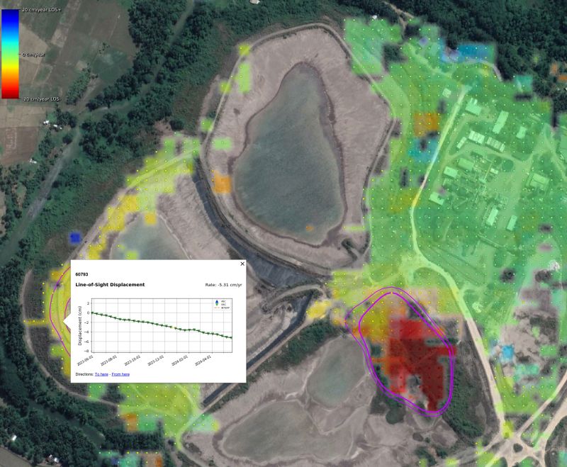 On LinkedIn, one can see numerous posts where independent experts are examining historical InSAR data for recent failures to see whether any early movement should have been detected. The results seem to be quite positive in that zones that have failed might have been red-flagged in advance.
They have also seen zones that showed critical displacements but have not failed (yet).
Typically, there are four ways to monitor displacement in pit slopes, tailings dams, heap leach pads, and waste dumps. They are:
-
Insitu monitoring using embedded instruments, for example slope indicators, extensometers, and settlement gauges. These instruments provide information on what is happening internally within a slope, where actual movement is occurring, and they can be used in warning alert systems.
-
Surface monitoring using radar (ground based InSAR) systems and laser survey prisms. These tools measure only surface movements in selected areas, can be monitored as frequently as needed on an automated basis, and can be integrated into warning alert systems.
-
Drone or aerial surveys can be used to measure topography and monitor movements over large areas. This method requires a data processing delay (not real time) to derive the movement information, but such surveys can be done as frequently as needed.
-
InSAR from satellite can be used over very large regions to highlight areas with movement. That should trigger the implementation of one or more of the other monitoring approaches (if not already in place).
Conclusion
 A mining site consists of numerous constructed embankments and slopes of all types and heights. Many of these slopes may be creeping and moving all the time – it’s a living beast.

 This is Part 2 of the blog post discussing junior mining scams and the sanctioning of those responsible. Part 1 can be found at this link “
 43-101 regulations state that “An issuer must not file a technical report that contains a disclaimer by any qualified person responsible for preparing or supervising the preparation of all or part of the report that
 This ends Part 2 of this blog post. It hopefully highlights the importance of QP’s being knowledgably on the disclosure rules and the technical aspects of what they are hired to do.
 In April 2024 Red Pine Exploration issued several press releases highlighting that some assays in their geological database were found to have been manipulated. Numerous assays input into their database did not match the original lab certificates. Is this another mining scam?
 The focus of this blog is on the types of activities that raised the red flags in the past. I am less interested in naming the people responsible, although the associated web links do provide more detail on the events.
 This ends Part 1 of this blog post. Part 2 will continue with a few more examples, specifically involving Qualified Persons, and can be found at this link
 Part 2 of this blog post will focus on the remaining engineering work to finish Chapter 16 of the Technical Report. We only wrote about half of it in Part 1. The mining engineer can generally handle the rest of these tasks in this Chwithout requiring a lot of external input. You can read Part 1 at this link “
 Two dilution approaches are common. One can either construct a diluted block model; or one can apply dilution afterwards in the production schedule. I have used both approaches at different times.
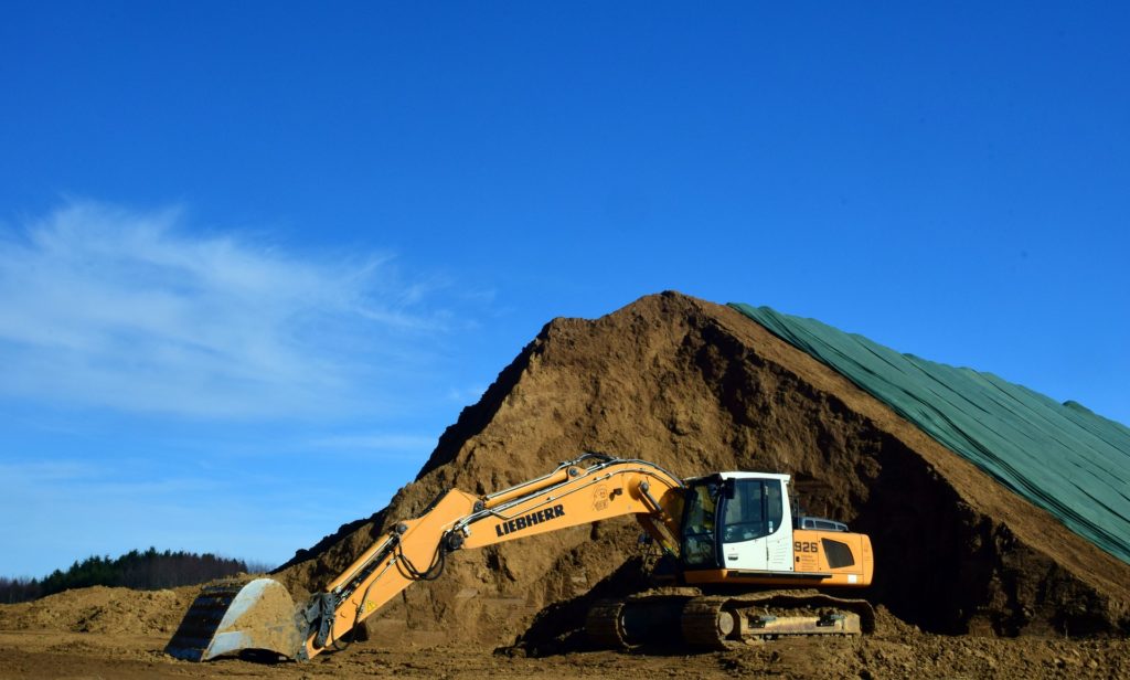 Sometimes lower grade stockpiles are built up by the mine each year but only processed at the end of the mine life. Periodically the ore mining rate may exceed the processing rate and other times it may be less. This is where the stockpile provides its value, smoothing the ore delivery to the plant.
 Once the production schedules are finalized, they are normally reviewed by the client for approval. The strip ratio and ore grade profile by date are of interest. One may then be asked to look to at different stockpiling approaches to see if an NPV (i.e. head grade) improvement is possible.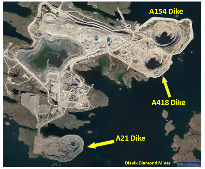
 The last task for the mine engineer in Chapter 16 is estimating the open pit equipment fleet and manpower needs. The capital and operating costs for the mining operation will also be calculated as part of this work, but the costs are only presented in Chapter 21.
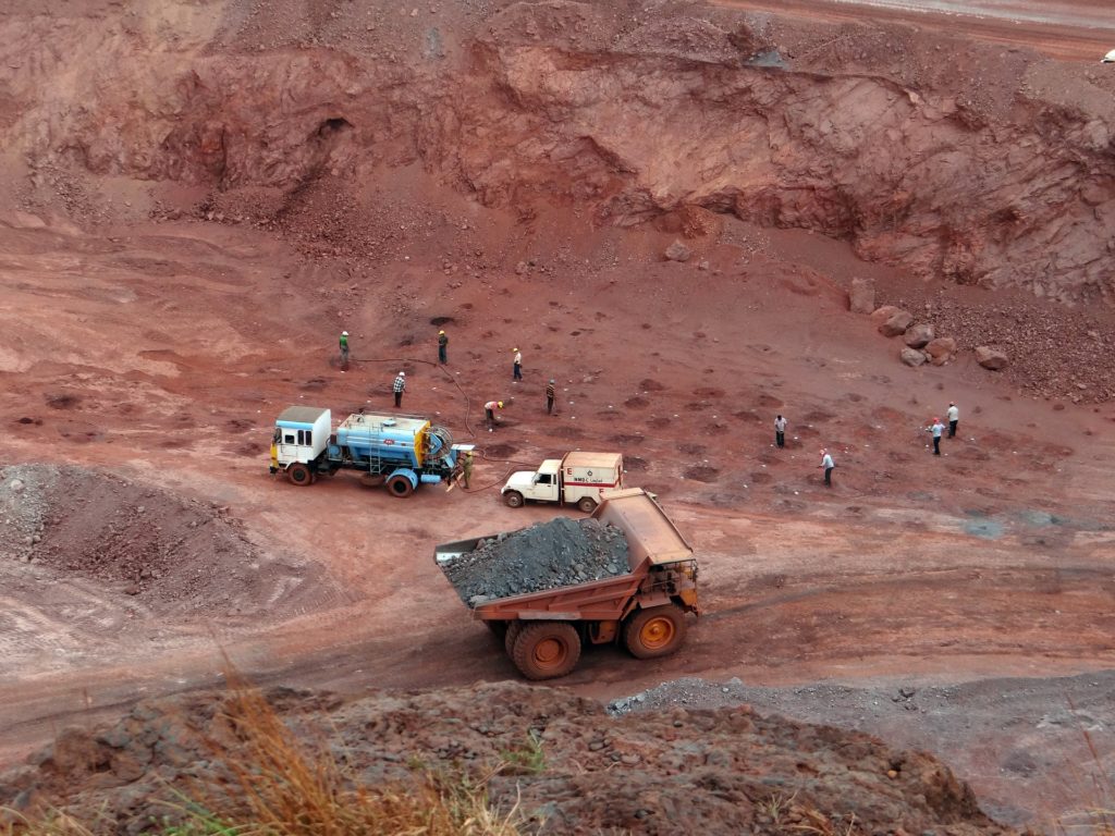 The support equipment needs (dozers, graders, pickups, mechanics trucks, etc.) are typically fixed. For example, 2 graders per year regardless if the annual tonnages mined fluctuate.
 These two blog posts give an overview of some of the things that mining engineers do as part of their jobs. Hopefully the posts also shed light on the amount of work that goes into Chapter 16 of a 43-101 report. While that chapter may not seem that long compared to some of the others, a lot of the effort is behind the scenes.
 Podcasts. There are thousands of them out there, free for anyone to access. This blog post is about the top mining podcasts that I find entertaining and educational. There are probably some missing from this list that I have not heard about. One only has so much free time in a day.
 Pick and choose wisely. One can’t listen to all the episodes available or else you wouldn’t have time to do anything else in life. You would also likely be bored because many can be similar and repetitive.
 Fresh Thinking by Optiro-Snowden
  There is no shortage of material in the podcast world about the mining industry. It all depends on what grabs your attention.
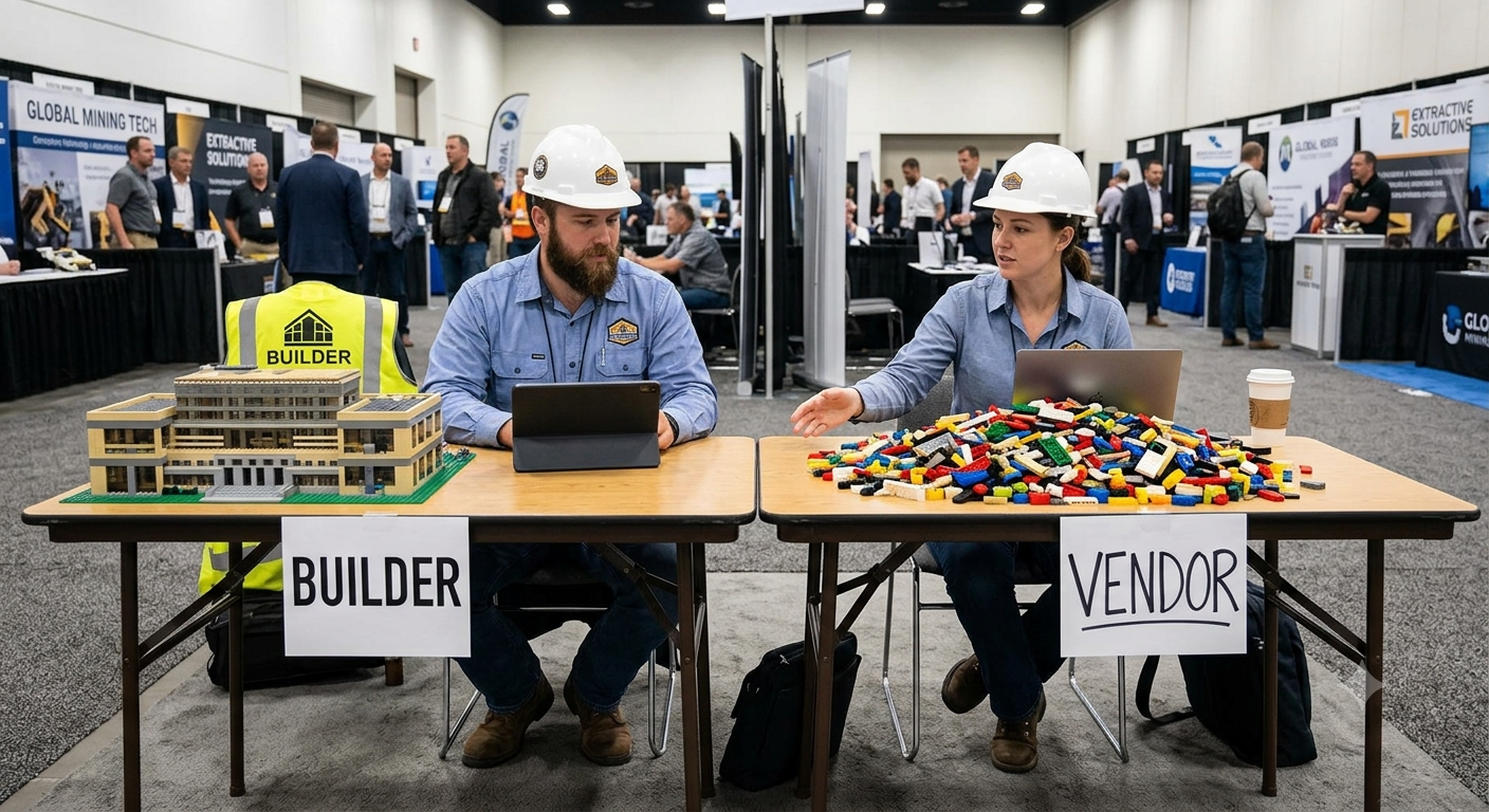 Normally Major and Intermediate miners advance their projects through the study stages with the ultimate intent to actually build the mine. Sometimes they may opt to sell their project if it no longer fits in their long term strategy or if they desperately need some cash. However, selling the project when it was first acquired was likely not their initial intent. They want to be on a Mine Builder path.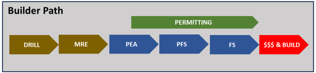
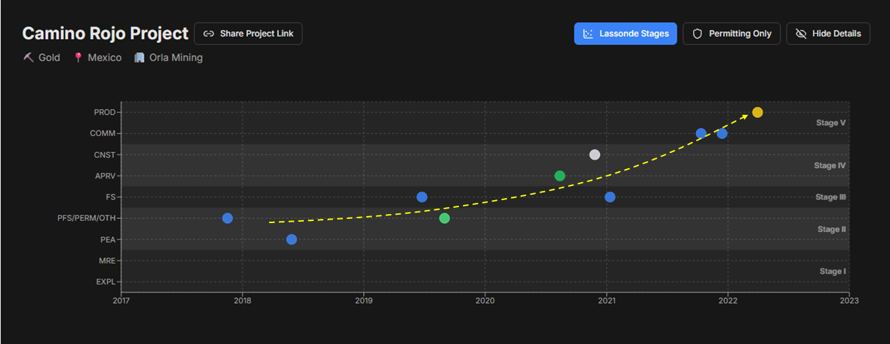
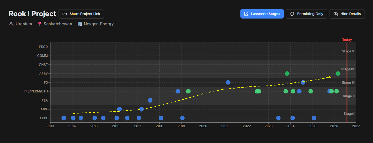
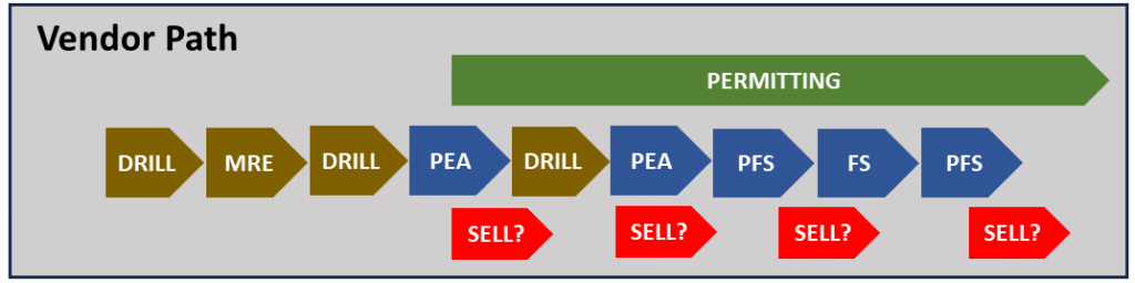
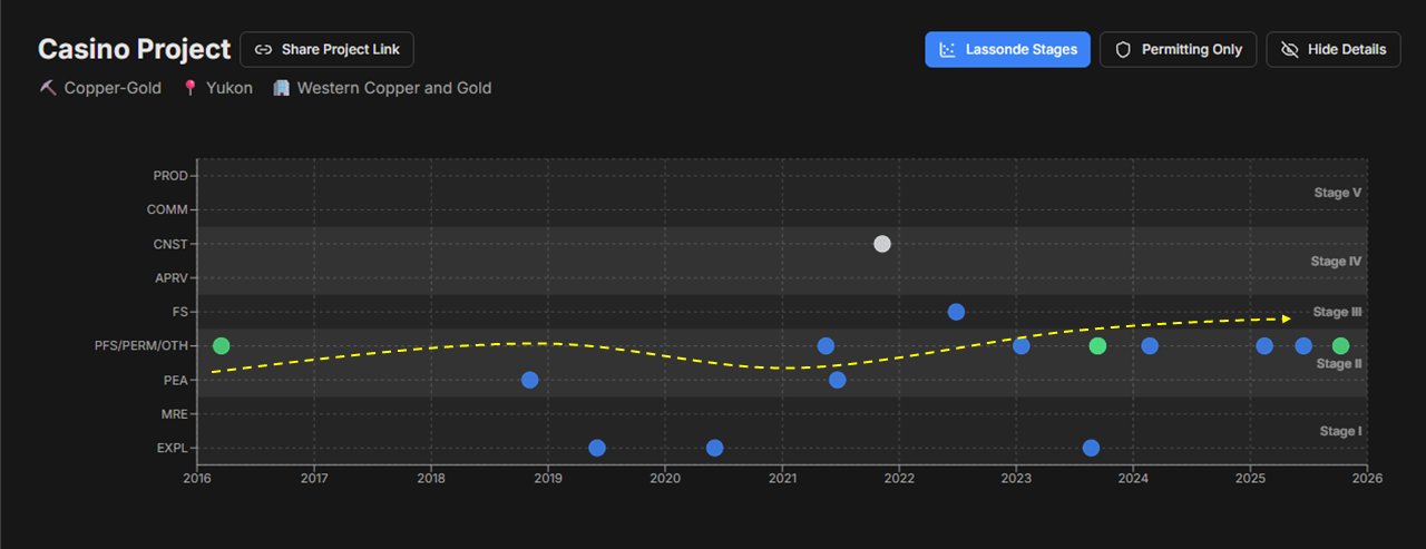
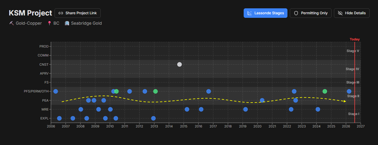
 If an engineer understands that a Mine Builder’s project will move from PEA to PFS to FS in rapid succession, then there is more incentive to ensure each study is somewhat integrated.
 The objective of the Mine Vendor is to make the project attractive to potential buyers. There is less urgency in fast tracking towards detailed engineering.
 As an engineer, it is helpful to understand the objectives of the project owner and then tailor the technical studies to meet those objectives. This does not mean low balling costs to make the study a promotional tool. It means focusing on what is important. It means recognizing the path, and what doesn’t need to be engineered in detail at this time. This may save the client time, money, and improve credibility in the long run.
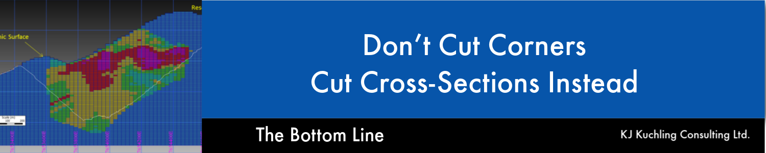
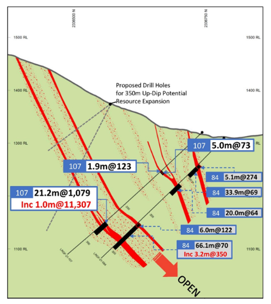 This article is about the benefit of preparing (cutting) more geological cross-sections and the value they bring.
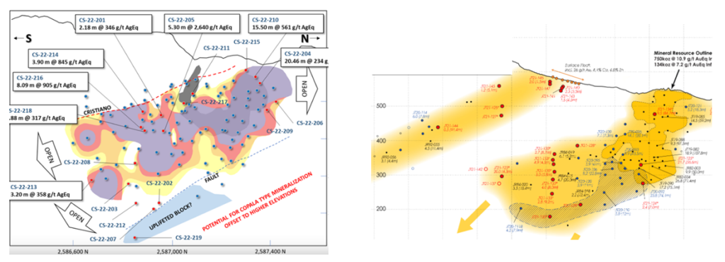 Long sections are aligned along the long axis of the deposit. They can be vertically oriented, although sometimes they may be tilted to follow the dip angle of an ore zone.
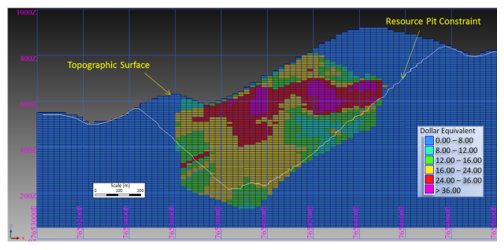 Cross-sections are generally the most popular geological sections seen in presentations. These are vertical slices aligned perpendicular to the strike of the orebody. They can show the ore zone interpretation, drill holes traces, assays, rock types, and/or color-coded resource block grades.
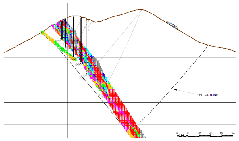 When looking at cross-sections, it is always important to look at multiple cross-sections across the orebody. Too often in reports one may be presented with the widest and juiciest ore zone, as if that was typical for the entire orebody. It likely is not typical.
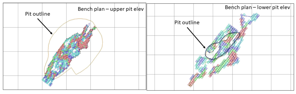 Bench plans (or level plans) are horizontal slices across the ore body at various elevations. In these sections one is looking down on the orebody from above.
 3D PDF files can be created by some of the geological software packages. They can export specific data of interest; for example topography, ore zone wireframes, underground workings, and block model information. These 3D files allows anyone to rotate an image, zoom in as needed and turn layers off and on.
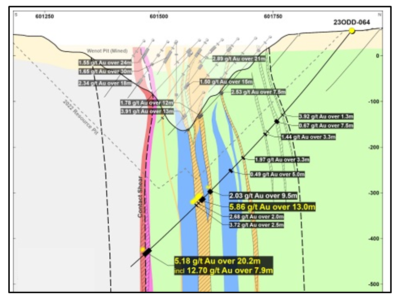 The different types of geological sections all provide useful information. Don’t focus only on cross-sections, and don’t focus only on one typical section. Create more sections at different orientations to help everyone understand better.
 When disclosing polymetallic drill results, many companies will convert the multiple metal grades into a single equivalent grade. I am not a big proponent of that approach.
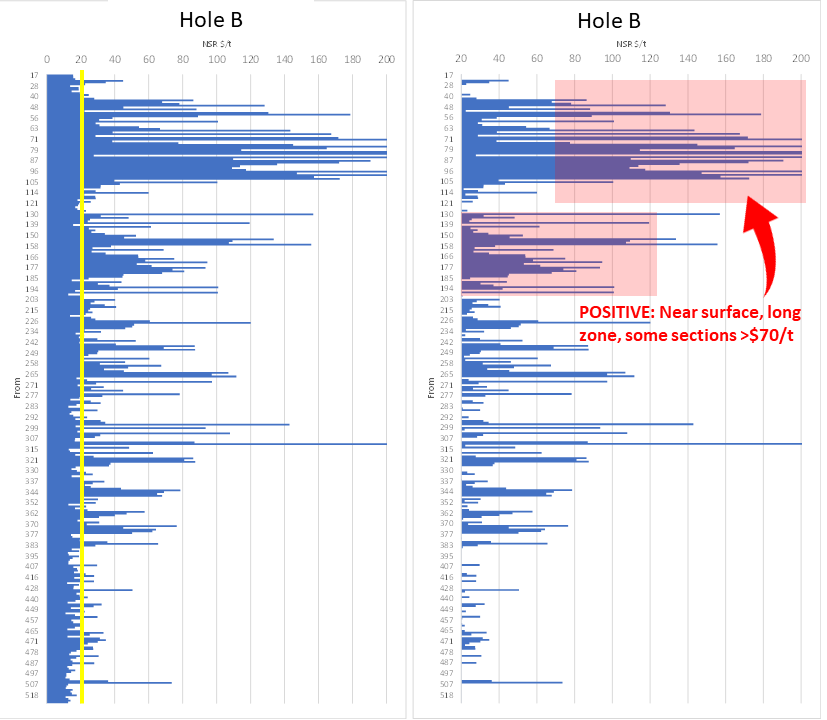
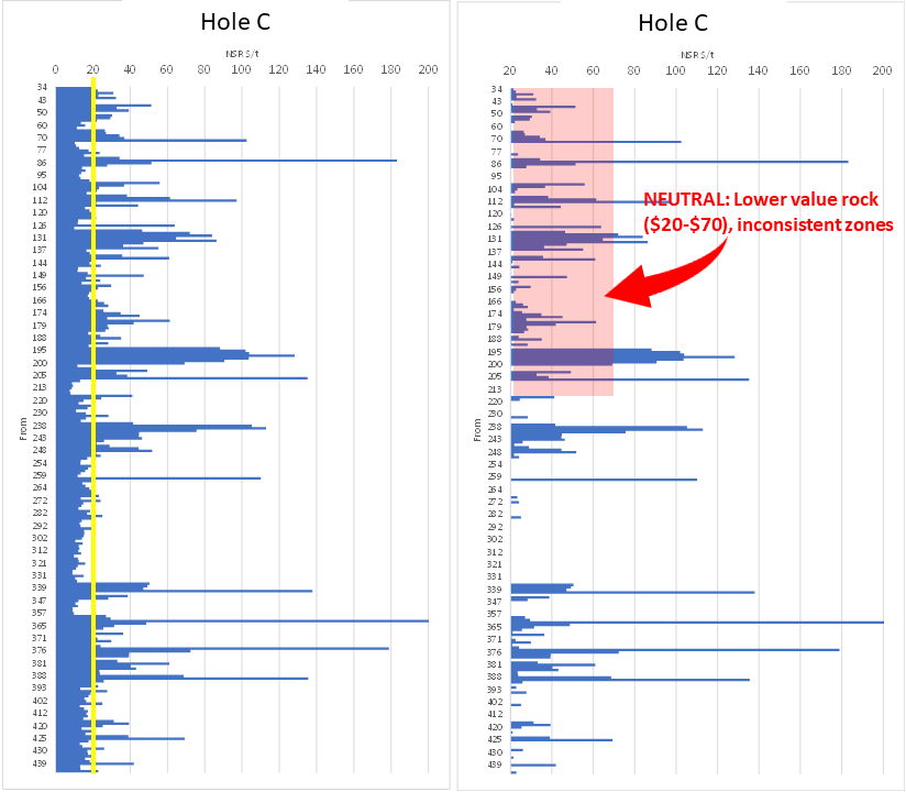
 The three aspects that interest me the most when looking at early-stage drill results are:
 The “NSR factor” would now be 85% x 85% or 75%. Therefore, if the breakeven cost is $14/t, then one should target to mine rock with an insitu value greater than $20/tonne (i.e. $14 / 0.75). This would be the approximate ore vs waste cutoff. It is still only ballpark estimate at this early stage, but good enough for this type of review.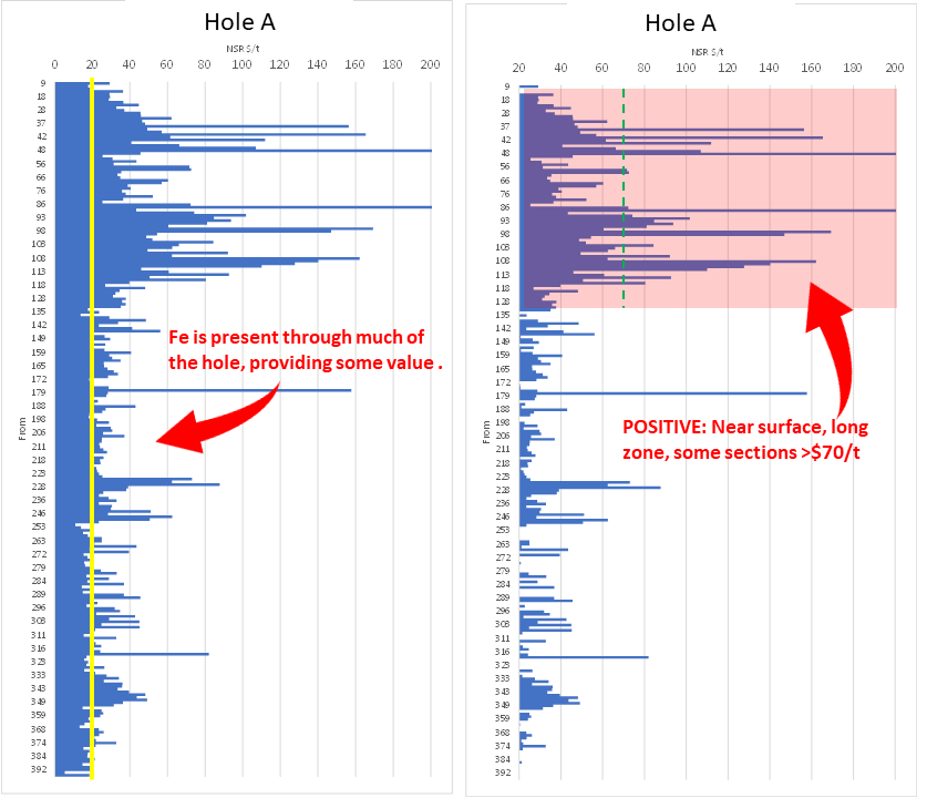


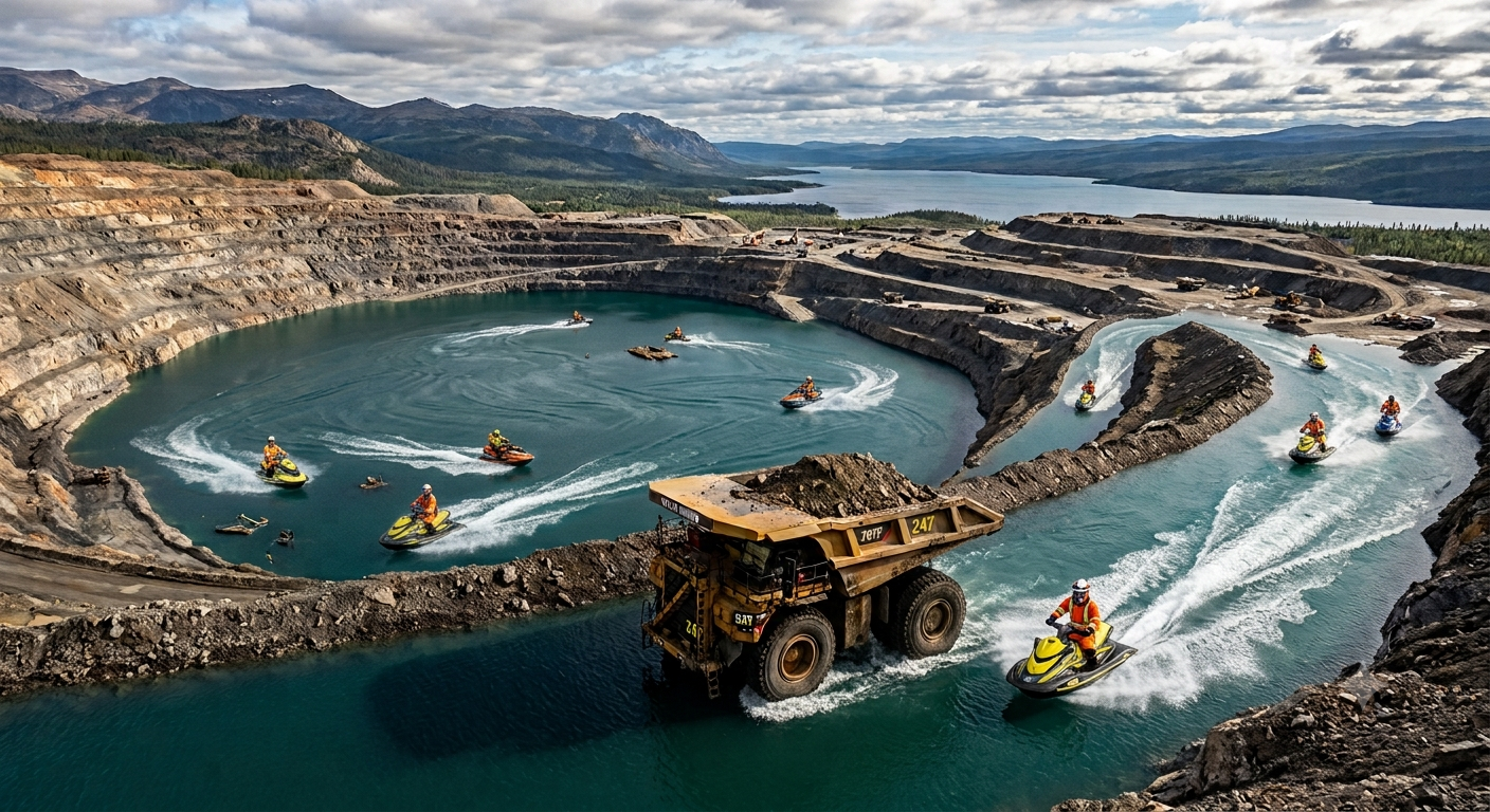 This is Part 2 of a blog post related to open pit mining within bodies of water. Part 1 can be found at this link “
 The primary question to be answered is whether one can mine safely and economically without creating significant impacts on the environment.
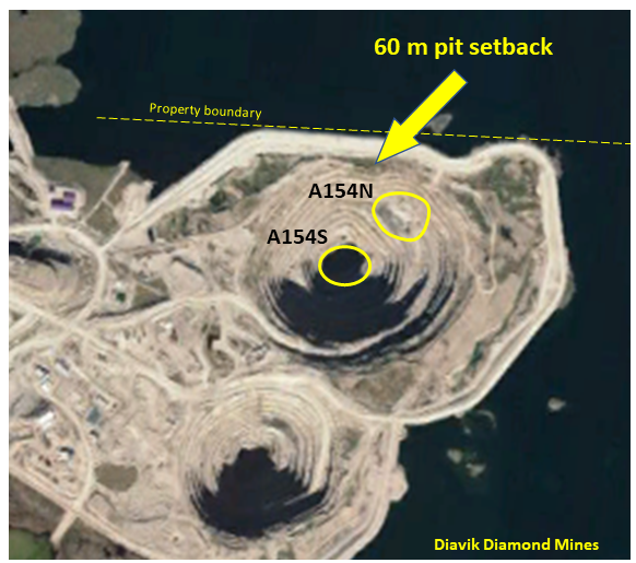
 Once the approximate location of the dike has been identified, the next step is to examine the design of the dike itself. Most of the issues to be considered relate to the geotechnical site conditions.
 Each mine site is different, and that is what makes mining into water bodies a unique challenge. However many mine operators have done this successfully using various approaches to tackle the challenge.