Articles tagged with: Underground

Hard Rock Continuous Cutting – Reducing Drill & Blast

Several years ago I worked in the Saskatchewan potash industry where I grew my appreciation for continuous mining systems. Some of the key benefits were the high productivity per man-hour and the safe operating conditions.  On a 12 hour nightshift, with a crew of 16 people we could mine over 9,000 tonnes of ore.  Productivity is  likely even higher now with the larger machines.   Therefore, since that time, I have always kept an eye out for when similar technology can be applied in hard rock mining.
One of the research areas we are seeing these days is the development of continuous cutting technology for hard rock mine development.  The idea is to replace the conventional drill & blast approach with something more efficient and safer.  No need to deal with explosives, noxious gases, shatter the wall rock, or have personnel scale their way under loose conditions.
Recently I was contacted by someone associated with Robbins asking if I was aware of their MDM5000 mine development technology.  I wasn’t aware of it, but I wondered if there finally is a light at the end of the tunnel.
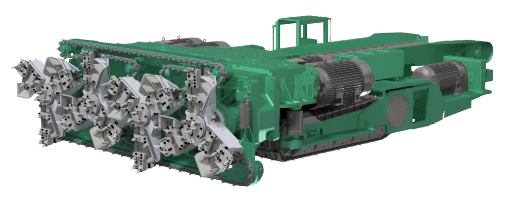
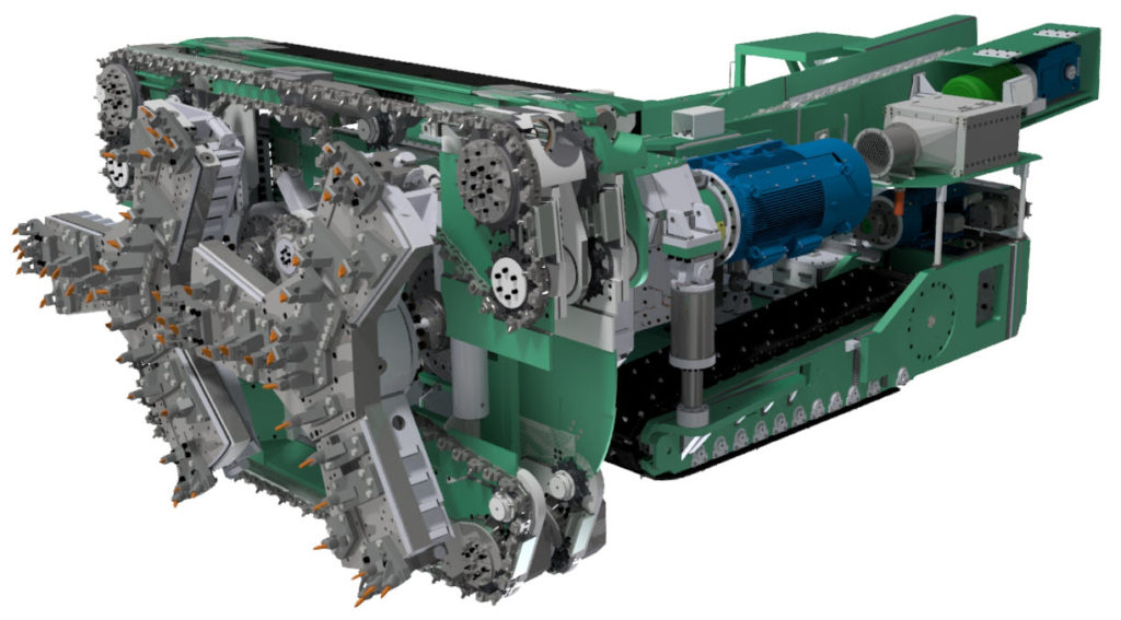
4-rotor miner

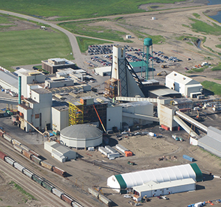
In Saskatchewan potash the entire mining operation relies on track-mounted continuous miner technology.   The miners are connected directly to the shaft area using a network of conveyors, up to 10 km worth of conveyor.
The potash miners are able to undertake both development work and production mining whilst connected to conveyor.
From time to time they will rely on shuttle cars, scooptrams, or grasshopper conveyors for small development tasks. A roadheader may also be available for localized ground stabilization.
All of this mechanical cutting is done in potash (sylvinite rock), considered a soft rock with a compressive strength of 20-40 MPa. For comparison, hard rock can have compressive strengths exceeding 250 MPa.

Two approaches in hard rock

Hard rock piloting trials are underway at a few operations, using different vendors with different equipment.  These trials include companies like Komatsu, Robbins, Sandvik, and Epiroc.  Each are testing their own equipment and cutting technologies.
The hard rock cutting approaches generally fall into two camps.

Roadheader style

There are the track mounted roadheader style cutters, typically with a movable arm used to shape the excavation.  Any excavation shape is possible.

Tunnel Borer Style

Then there are the tunnel borer styles, where the machine propels itself with hydraulic shoes and the opening shape is based on the machine configuration. Normally a circular shaped opening is the result.
The roadheader style cutter is normally restricted to softer rock (< 50 MPa) while the tunnel borer is capable of much harder rock (200-250 MPa).

Robbins MDM5000

One system that peaked my interest is the Robbins MDM5000 because it can both cut hard rock and create a rectangular opening. Speaking with the vendor, this unit uses shoes to propel itself while cutting a rectangular shaped opening about 5m x 4.5m in size (see image).  A rectangular shape is preferred to the circular opening whereby the floor invert must be backfilled to provide a level operating surface.

MDM5000 opening shape

The MDM5000 configuration and advance rate allows the installation of ground support and utilities behind the advancing face.   Water sprays and dust collectors help to maintain visibility and air quality at the working face.
The Robbins unit is best suited for long straight drives although reportedly it can turn curves with 450-m radius.  Tighter turns may be feasibility in the future by tweaking the machine design.   Interestingly driving a drift uphill is easier than driving downhill due to the more efficient cuttings removal capability.
The MDM5000 unit can be linked to a Robbins conveyor system, which includes a head drive and an extensible belt storage unit that can feed out the conveyor belt as the machine advances forward.  This operation is similar to that used in the Saskatchewan potash industry.

Robbins MDM5000

A Robbins machine has been in operation at the Fresnillo mine for several years with favorable results (check out the link here).
One nice thing about disc cutters is that they can accommodate variable rock types (softer and harder) while road headers can be hindered by hard rock zones.  Roadheaders require a bit more consistency in rock quality.
Continuous cutting systems, such as the MDM5000, can be combined with vertical conveying technology, leading to safe and rapid development (>200m per month) in the right situation.

Conclusion

No doubt that we will eventually see more application of hard rock continuous cutting technology in the right situations.  The Stillwater Mine in Montana has been using a Robbins tunnel borer for years for development tasks.
No matter how well these new systems perform, there will still be some limitations.  This means the conventional drill and blast development will always be around.  However, keep your eyes on this mining technology sector as improvements in cutter head design and equipment mobility continue to evolve.
Coincidentally International Mining (Nov-Dec 2021) recently published an in-depth article on the various systems being looked at.  The link is here.


Note: You can sign up for the KJK mailing list to get notified when new blogs are posted.   Follow me on Twitter at @KJKLtd for updates.
Share

Potash Stories from 3000 Feet Down – Part 2

This is Part 2 of my story about working at a potash mine in Saskatchewan. If you haven’t read Part 1, here is the link to it “Potash Stories from 3000 Feet Down – Part 1“.  It’s best to read it first.

Flooded Russian Potash Mine

As mentioned in Part 1, water seepage and potential leaks were always an operational concern. There were essentially two main fears; (i) that a borer would tunnel into an unforeseen collapse zone (i.e. an ancient sink hole) or (ii) that long term deformations in the mine would result in cracking of the overlying protective salt layer resulting in water inflow.
Any time wet spots were seen on the roof, the mining engineers or geologists were called out to take a look.
Sometimes the wet area was due to pockets of interstitial moisture. Other times it might have just been oil from a blown hydraulic hose on the borer. Wet spots all look the same when covered in dust.
Water ingress was such a concern in that an unmined pillar of 100 ft. would be left around all exploration core holes. These 3,000 ft. holes were supposedly plugged after drilling but you could never be certain of that. Furthermore, you couldn’t be certain of their location at potash depth. Hence, we didn’t want to mine anywhere close to them.
The process plant also had several water injection wells whereby excess water was injected into geological formations deep below the potash level. We left a 700 ft. pillar around these injection wells.
Carnallite is a magnesium salt that we encountered in some areas of the mine. It was weaker than the halite, resulting in more rapid room closure and deteriorating ground conditions. It was also hydroscopic and could absorb moisture out of the air. Sometimes we would water the underground travel ways to mitigate dust issues. With the resulting high humidity sometimes the carnallite areas might start to drip water. This resulted in another call to the engineers to come out and investigate.

Working on a production crew brings new learnings.

My period as a production foreman was great. When first assigned to this role, I was less than enthusiastic but when it was over 6 months later, I appreciated the opportunity. As a production foreman, we had a crew of 15 to 20 people responsible for mining 9,500 tons over a 12 hour shift. There was one foreman in the underground dispatch room and one face foreman travelling around supervising the borers and inspecting conveyors.
Ore grade control was a key responsibility of both the borer operator and mine foreman. The goal for the borer operator was to cut the roof even with the top of the high grade potash bed. The goal for the foreman was to ensure the operator was maintaining his goal. However, when looking at the potash face all the beds generally looked the same, especially when they are dusty.

Feel the glow

One key distinction was that the middle low grade bed had a higher percentage of insol clays. It was used as a marker bed. You would take your hardhat lamp and run it down against the wall. In the upper high grade potash bed, the cap lamp would have a halo, not unlike like the glowing salt rock lamps you see in stores. In the marker bed the halo would disappear, like putting a lamp against a rock wall.
Thus using the lamp you could identify the top of the marker bed, which was supposed to be kept 3.5 to 4 ft. off the floor. If borer operators were consistently more than 12 “ inches off optimal level, they could be written up (i.e. reprimanded). This was one of my tasks as foreman and I always hated doing it.
Lasers were used to guide the borer in a straight line but the marker bed was used for vertical control. Nowadays the use of machine mounted ore grade monitors is an option. By the way, if you’re looking at a potash project, be aware of the grade units being reported. A previous blog discusses this “Potash Ore Grades – Check the Units”.
The underground conveyor network consisted of 32” conveyors, feeding onto 42” conveyors, feeding on to 48”or 54” conveyors. Typically the length of the larger conveyors was in the range of a mile (5,000-6,000 ft.). The conveyors were all roof mounted, allowing for easy clean up underneath. Roof mounting was critical. Even some of the 600 hp conveyor drive stations were roof mounted, structure and all.

Conveyors were the reason for my one and only safety incident.

4-rotor side pass

4-rotor borer side pass

First a little background. The underground ore storage capacity at K1 was about 3,000 tons. If the underground bins were filled anytime during a shift, the entire conveyor system would automatically trip off; all 10 miles of it. If you happened to have a mile long conveyor shut off while it was loaded to the brim with ore, good luck starting it up again.
If this happened, there were two choices. You could bring in the operators from the borers to start shovelling off the conveyor until it was unloaded enough to re-start. This option went over like a lead balloon with the crew.
The other not so great option was to use a scooptram to lift the belt counterweight up to reduce the belt tension. This allows the drive pulleys to start spinning. Then by lowering the counterweight back down perhaps the drives can inch the belt along. The idea being that possibly the momentum of the moving mass of potash would keep it moving. The downside is that you could break the belt. There was nothing worse than having to tell the cross shift they have both a stalled conveyor and a broken belt. Have a good shift people.
At 4 a.m. working as night shift face foreman, I knew the underground bins were nearing full. Driving along I saw that the mainline conveyor was full and spilling over the sides. A worst case conveyor shutdown was imminent. I called the dispatch office to ask why he hasn’t been shutting down borers and conveyors but there was no answer.
After several unanswered calls I started to hustle back to dispatch. I remember driving alongside the conveyor thinking “don’t shut off, don’t shut off”. Just then a heavy duty service vehicle pulled out of a cross-cut and I plowed right into it. I wasn’t going very fast (~20 km), but when a Toyota Land Cruiser hits a steel plate truck, the Toyota is the loser. The front end crumpled, and I later was told that there was major frame damage.
I’m not sure why the other driver didn’t see my lights. I’m also certain his lights were not on. Nevertheless, I did get written up for this incident with a reprimand for my personnel file. The reprimander had become the reprimandee. I still insist that the incident wasn’t my fault.
The Land Cruiser laid around the shaft for a few days until it could be hoisted up to surface. Everyone coming on shift got to see it . Once it was hoisted up, it laid outside the headframe for a few more days for all the surface workers to see. Ultimately, this incident resulted in the underground miners giving me the nickname “Crash”.
This is where I’ll end the potash story.

Conclusion

Saskatchewan potash is a unique mining situation. It has its own history and mining method. The people are great and it’s a great place to learn the difference between engineering school and real life.

Mine Engineering Dream Team

By the way, I also learned that small town Saskatchewan loves their senior hockey league (20-30 year age range). The local towns compete all winter; sometimes combatively. It was Esterhazy vs. Langenburg vs. Whitewood vs. Rocanville vs. Stockholm vs. Moosomin.
One of the first questions asked in my job interview at Mosaic was if I played hockey. You see, the ideal candidate for the job would have been an ex-NHL player, preferably an enforcer, who is also a mining engineer. Gotta stack the local team.
If you enjoy reading these types of stories about working as an engineer, there is an entire book on the subject, written by a former colleague of mine.  You can learn a bit more about this civil engineer’s experiences working around the global at this link “Life as an Engineer – Read All About It”


Note: You can sign up for the KJK mailing list to get notified when new blogs are posted. Follow me on Twitter at @KJKLtd for updates and insights.
Share

Potash Stories from 3000 Feet Down – Part 1

Mosaic K1 Mine

Between 1985 and 1989 I worked at the Mosaic K1 potash mine in Saskatchewan, Canada.  I had roles that included mine engineer, chief mine engineer and production foreman.   This was relatively early in my work career so it represented an important learning period of time for me.
Each of these roles gave me a different perspective about a mining operation.   In this two part blog, I’ll share some stories relating to the uniqueness of potash mining.
The K1 mine is 15 kilometres outside the town of Esterhazy; about 2.5 hours east of Regina.  The mine is located at a depth of around 3,000 feet below surface, hence the title of this blog.
I will be referring to imperial units in this text because when the mine started production in the early 1960’s the maps and units were imperial and continued on through the 80’s.   At my previous job with Syncrude we used metric units, so it took some time to mentally recalculate back.
Geologically, the province wide Esterhazy Member was being mined, named after the town.  The layer was about 8 ft high.  In other regions of Saskatchewan they are mining a different potash layer (the Patience Lake Member) which is located a few feet higher up. These mines have slightly different mining conditions than we experienced in Esterhazy.  An example of their conditions is shown in the photo, where a parting layer can result in a roof collapse.
The Mosaic K1 and K2 mine shafts are interconnected at depth 6 miles.  The total expanse of the K1 and K2 underground workings probably extends laterally over 18 miles.  Back in the 80’s they said there were over 1,000 miles of tunnel underground and probably a lot more now since the mines are still operating.  There is now a new K3 shaft which allows access to more distant potash reserves.

4-rotor borer

Potash, also termed sylvanite, mainly consists of intermixed halite (rock salt) and sylvite (potash) crystals. There are also minor amounts of insolubles (clays) and sometimes carnallite (a magnesium salt).  Sylvite (KCl) is the pay dirt, salt is the gangue mineral.
The production rooms being mined were about 75 ft. wide and 5,000 ft. long.  That is quite a large span, not likely possible in many other rock types other than salt rock.  Overall, the mine would extract about 40-45% of the potash, leaving behind the rest in the form of large pillars to support the overlying rock mass.

2-rotor borer

The mines use continuous miners or borers. In the 80’s they were Marietta miners and now they use borers from Prairie Machine (read more here).   When I was there they were starting to transition from two-rotor to four rotor machines.   The small machines would carve out ~350 tph, and the large ones could do over ~700 tph.
All borers are directly connected to the massive underground conveyor network that moves the ore from the cutter head to the shaft in a continuous process.
Mining excavates an 8 ft. high room consisting of three layers of interest.  A 4.3 ft. layer of high grade ore, a 1.7 ft. layer of low grade ore, and a 2.5 ft. layer of moderate grade potash.  This adds up to 8.5 ft., so the miners try to take the best 8 feet.  The best head grade would be delivered if the borer cut exactly to the top of the high grade 4.3 ft. seam. One didn’t want to overcut into overlying salt or undercut and leave high grade behind in the roof.  I’ll have more on how grade control was done in Part 2.
The air temperature underground is about 25C, so it’s quite a pleasant short sleeve climate.  Around the cutting face, the electric motors, and cutter head, temps can reach into the high 30 degree range. Hot but better than freezing. The mine was dry with very low humidity.   Hence metal didn’t rust.  However, bring the metal to surface and it would rust in no time.
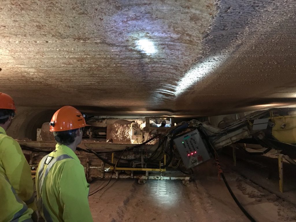
Potash is termed a plastic rock, in that it will deform slowly under stress.  Hard rock will build up stresses and erupt violently in a “rock burst”.  Potash will go with the flow and deform.  Pillars will compress vertically and expand horizontally.  Room heights can decrease over time as much as 6 inches over several weeks in higher stress areas.
Interestingly when the borer shut down and all was quiet, one could walk to the freshly cut face.   You could hear the potash walls gently crackling like rice krispies, as the potash expanded into the opening.  After all, a few moments earlier the potash was being laterally confined under a vertical stress of 3,000 psi. That confinement is suddenly gone.
Roof closure was always an issue.  In panels that were almost mined out, all the ground stress was being carried by the unmined ground.  When advancing into this ground, roof closure could be so rapid that once a borer finished a 4 to 6 week room, the miner operator would need to cut a few inches off  the roof to get back to the front of the room.  It took a couple of days to get the borer out, rather than during a regular shift.
In very high stress areas you could see the floor heaving up as pillars were compressing laterally. That’s when you really knew that mining panel was done and operations should relocate to a new area.
I recall inspecting some of the very old workings from 20 years past.  The rooms looked like new except the roof had compressed down to 5 ft. in height.   We’d have to drive leaning sideways out of the jeep because the steering wheel was literally scraping the roof.

Flooded Russian Potash Mine

The biggest fear in potash mining is water inflow and mine flooding. There can be a water bearing layer about 50-70 feet above the mining level.  A layer of salt rock separates the two.
If you have groundwater flowing through a dissolvable material, it’s no surprise that the pathway will keep getting larger and larger. That’s why any sign of water seepage is taken seriously and causes the engineering team to leap into action (more on that in Part 2).
At least one potash mine in Saskatchewan has flooded.  A couple of others have come close but have managed to deal with the water inflows.
Barren areas where the sylvite has been leached away and replaced with pure halite are called salt horses.   I never knew why and still don’t.
Exploration core holes could be a mile apart so salt horses would be encountered unexpectedly.  They could be 20 or 2,000 feet in size; you never knew which.   They were a nuisance and an economic penalty.  If you tried to tunnel through them, you would send a lot of uneconomic salt up the shaft to the mill (which they did not like).
Conversely, pulling out and abandoning a room was a painful decision because it took that borer off line for a couple of days to relocate. It’s an unplanned outage, which is not good if another borer happens to be moving at the same time.
On occasion, a borer would abandon the room and move to the next room 50 feet away and could pass by the same area without seeing the salt horse.  Upon reflection, perhaps we should have persevered in the previous room and gone another 20 ft. and we might have been through it.  Often the mill manager hollering about the mill getting too much salt was a deciding factor in whether to abandon a room or keep cutting.
For a year or so,  I also worked as a production foreman.  It was an interesting role. How does a young mining engineer four years out of school tell  guys working underground for 20 years what they need to do?
This also leads to the time when I wrecked a Toyota Land Cruiser underground.   I’ll leave that account to Part 2.  I’ve rambled long enough for today.  You can read Part 2 at this link “Potash Stories from 3000 Feet Down – Part 2″.
Note: You can sign up for the KJK mailing list to get notified when new blogs are posted.   Follow me on Twitter at @KJKLtd for updates and insight.
Share

Two Mining Innovations – Load Scanning & Vehicle Tracking

The mining industry is always on the lookout for new innovations as it strives to keep up with other industries.  In that light, periodically I like to highlight new technologies that I become aware of.   I’m trying to help spread the word  about them, which in turn may assist them in their on-going growth and development.
In this article I want to briefly describe two hardware / software companies that are working on technologies related to mine equipment productivity.    In no particular order, the two companies are Loadscan and SedimentIQ.  SedimentIQ is more of a startup than Loadscan which has a longer operating track record.
These technology companies are both targeting the open pit and underground markets, looking to provide simpler and less costly productivity solutions. Their technologies may be well suited for small to mid tier mines that cannot afford or don’t require the comprehensive Minestar type fleet management systems.
For the record, I get no fee or commission for promoting these companies; I just like what they are doing.

Loadscan

Loadscan has been around for a few years, but I only became aware of it recently.  It is a technology that allows the rapid assessment of the load being carried in truck.  It does not rely on the use of load cells or weigh scales to measure the payload.
Instead Loadscan uses a laser scanner and proprietary software to three dimensionally map the surface of the truck payload and then calculate its volume.  The results will indicate how consistent and optimal truck loading is volumetrically.   One can then calculate the payload tonnage by applying a bulk density.
The Loadscan technology will assess whether trucks are being over or under loaded, whether the loads are off-centre, or whether there is excess carryback on the return trip.
Successive truck payloads can be tracked manually or with RFID tags.   A cloud based database and web based dashboard are used to store the data and summarize it. The output can include an image of each individual load.
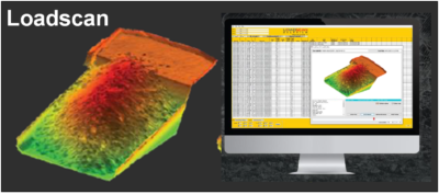
What is interesting about this technology is that it is simple to install in an operation.  It does not require retrofitting of a truck.
Results are immediate.  Loadscan provided an example where a message readout board can let the shovel operator immediately know how well each truck was loaded, resulting in improved education and better performance efficiency.
One can also assess how much better shovel bucket factors are in well blasted rock versus in blocky rock.
The Loadscan system is already in use in several mines globally.  The vendors can provide more technical  data if you need it.
Their website is https://www.loadscan.com/

SedimentIQ

SedimentIQ is a new smartphone vehicle tracking platform that is trying to establish itself.  Their proposed technology makes use of a phone’s built-in GPS, Bluetooth, and accelerometer to track vehicle operation.  The phone’s sensor can measure vibrations produced by an operating truck or loader.
Vibration is a fingerprint of a vehicle’s activity.  Therefore using machine learning, the SedimentIQ app can produce an “activity score” that decides whether a machine is parked, idling, or performing productive work.  The phone is not connected to the machine diagnostics system, so its very easy to install, only needing a power source.
The system will be able to be used on any vehicle, including trucks, drills, loaders, graders, dozers, etc. The system has the capability to monitor equipment location and speed.
In an open pit environment it uses the phone’s GPS to monitor vehicle location. In an underground setting the phone reads inexpensive Bluetooth beacons mounted along the side walls to track location.
The app will identify delay and downtime based on equipment vibration levels.  The system currently requires no interaction with the operator, working in the background.  Hence it will not identify the cause of delay (i.e. blasting delay, breakdown, inter-equipment delay, etc).  I would expect that in the future they could add a feature for the operator to tag delay types on the touch screen.
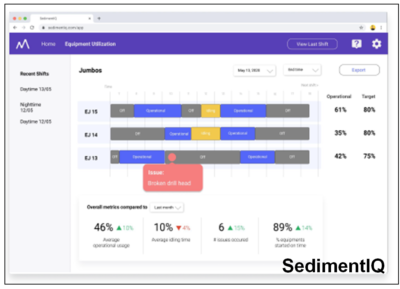
The SedimentIQ software will aggregate the cycle time and delay information and upload it in real time to a cloud based database.  A web-based dashboard allows anyone with access to view the real time production data graphically or export it to Excel.
The SedimentIQ platform is less expensive than high end fleet management software.  Although it may not provide all the bells and whistles of the high end software, it may deliver just what you need to monitor productivity in your mining operation.  It relies on relatively inexpensive smart phones that are locked to the application.
I recall as a mining student doing time studies.  I rode the shift crew bus with pencil in hand, timing the travel  from the mine dry to the various shovels to measure start up times.  I recall sitting with a stopwatch timing shovel buckets and truck loading times.  Both of these tasks can be done for every shift, every truck by equipping the crew bus and mine trucks with the SedimentIQ tech.
The platform is currently being tested at a couple of trials mines and the founders are looking for more mines willing to adopt and further refine their technology.  Lets hope they can make a successful go of it.
The website is https://sedimentiq.com/.

Conclusion

Both of these innovative technologies can provide useful information to open pit and underground mine operations.  They are in the growth stage, looking for wider adoption.   Input from users, whether positive or negative, will assist them with on-going development and enhancements. Their websites obviously have more on what their technology offers, including presentations, white papers, and case studies.
It would be nice to meld these two technologies in some way to allow the SedimentIQ cycle times to also track payloads.
Check them out.  Try them out.


Note: You can sign up for the KJK mailing list to get notified when new blogs are posted.   Follow me on Twitter at @KJKLtd for updates and insights.
Share

O/P to U/G Cross-Over – Two Projects into One

Over the years I have been involved in numerous mining tradeoff studies. These could involve throughput rate selection, site selection, processing options, tailings disposal methods, and equipment sizing. These are all relatively straightforward analyses. However, in my view, one of the more technically interesting tradeoffs is the optimization of the open pit to underground crossover point.
The majority of mining projects tend to consist of either open pit only or underground only operations. However there are instances where the orebody is such that eventually the mine must transition from open pit to underground. Open pit stripping ratios can reach uneconomic levels hence the need for the change in direction.
The evaluation of the cross-over point is interesting because one is essentially trying to fit two different mining projects together.

Transitioning isn’t easy

There are several reasons why open pit and underground can be considered as two different projects within the same project.
There is a tug of war between conflicting factors that can pull the cross-over point in one direction or the other. The following discussion will describe some of these factors.
The operating cut-off grade in an open pit mine (e.g. ~0.5 g/t Au) will be lower than that for the underground mine (~2-3 g/t Au). Hence the mineable ore zone configuration and continuity can be different for each. The mined head grades will be different, as well as the dilution and ore loss assumptions. The ore that the process plant will see can differ significantly between the two.
When ore tonnes are reallocated from open pit to underground, one will normally see an increased head grade, increased mining cost, and possibly a reduction in total metal recovered. How much these factors change for the reallocated ore will impact on the economics of the overall project and the decision being made.
A process plant designed for an open pit project may be too large for the subsequent underground project. For example a “small” 5,000 tpd open pit mill may have difficulty being kept at capacity by an underground mine. Ideally one would like to have some satellite open pits to help keep the plant at capacity. If these satellite deposits don’t exist, then a restricted plant throughput can occur. Perhaps there is a large ore stockpile created during the open pit phase that can be used to supplement underground ore feed. When in a restricted ore situation, it is possible to reduce plant operating hours or campaign the underground ore but that normally doesn’t help the overall economics.
Some investors (and companies) will view underground mines as having riskier tonnes from the perspective of defining mineable zones, dilution control, operating cost, and potential ore abandonment due to ground control issues. These risks must be considered when deciding whether to shift ore tonnes from the open pit to underground.
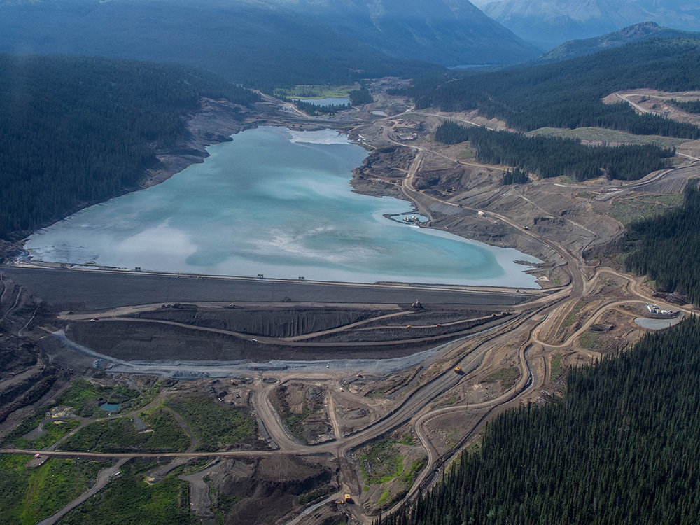
An underground mine that uses a backfilling method will be able to dispose of some tailings underground. Conversely moving towards a larger open pit will require a larger tailings pond, larger waste dumps and overall larger footprint. This helps make the case for underground mining, particularly where surface area is restricted or local communities are anti-open pit.
Another issue is whether the open pit and underground mines should operate sequentially or concurrently. There will need to be some degree of production overlap during the underground ramp up period. However the duration of this overlap is a subject of discussion. There are some safety issues in trying to mine beneath an operating open pit. Underground mine access could either be part way down the open pit or require an entirely separate access away from the pit.
Concurrent open pit and underground operations may impact upon the ability to backfill the open pit with either waste rock or tailings. Underground mining operations beneath a backfilled open pit may be a concern with respect to safety of the workers and ore lost in crown pillars used to separate the workings.
Open pit and underground operations will require different skill sets from the perspective of supervision, technical, and operations. Underground mining can be a highly specialized skill while open pit mining is similar to earthworks construction where skilled labour is more readily available globally. Do local people want to learn underground mining skills? Do management teams have the capability and desire to manage both these mining approaches at the same time?
In some instances if the open pit is pushed deep, the amount of underground resource remaining beneath the pit is limited. This could make the economics of the capital investment for underground development look unfavorable, resulting in the possible loss of that ore. Perhaps had the open pit been kept shallower, the investment in underground infrastructure may have been justifiable, leading to more total life-of-mine ore recovery.
The timing of the cross-over will also create another significant capital investment period. By selecting a smaller this underground investment is seen earlier in the project life. This would recreate some of the financing and execution risks the project just went through. Conversely increasing the open pit size would delay the underground mine and defer this investment and its mining risk.

Conclusion

As you can see from the foregoing discussion, there are a multitude of factors playing off one another when examining the open pit to underground cross-over point. It can be like trying to mesh two different projects together.
The general consensus seems to be to push the underground mine as far off into the future as possible.  Maximize initial production based on the low risk open open pit before transitioning.
One way some groups will simplify the transition is to declare that the underground operation will be a block cave. That way they can maintain an open pit style low cutoff grade and high production rate. Unfortunately not many deposits are amenable to block caving.  Extensive geotechnical investigations are required to determine if block caving is even applicable.
Optimization studies in general are often not well documented in 43-101 Technical Reports. In most mining studies some tradeoffs will have been done (or should have been done).  There might be only brief mention of them in the 43-101 report. I don’t see a real problem with this since a Technical Report is to describe a project study, not provide all the technical data that went into it. The downside of not presenting these tradeoffs is that they cannot be scrutinized (without having data room access).
One of the features of any optimization study is that one never really knows if you got it wrong. Once the decision is made and the project moves forward, rarely will someone ever remember or question basic design decisions made years earlier. The project is now what it is.


Note: You can sign up for the KJK mailing list to get notified when new blogs are posted. Follow me on Twitter at @KJKLtd for updates and insights.
Share

Vertical Conveyors Give Mining a Lift

There are not many things that are novel to me after having worked in the mining industry for almost 40 years.  However recently I came across a mining technology that I had heard very little about.  It’s actually not something new, but it has never been mentioned as a materials handling option on any project that I am aware of.
That innovative technology is vertical conveying. Not long ago I read about a vertical conveyor being used at the Fresnillo underground mine, hoisting 200 tph up from a depth of 400 metres and had a capital cost of $12.7 million.
I was aware of steep angle conveyors being used in process plants.  However they tended to be of limited height and have idlers and hardware along their entire length. Vertical conveyors are different from that.
After doing a bit of research, I discovered that vertical conveyors have been used since the 1970’s.  Their application was mainly in civil projects; for example in subway construction where one must elevate rock from the excavation level up to street level.   The mining industry is taking vertical conveyors to the next level.
I have never personally worked with vertical conveyors.  Therefore I am providing this discussion based on vendor information.  My goal is to create awareness to readers so that they might consider its application for their own projects.

How vertical conveying works

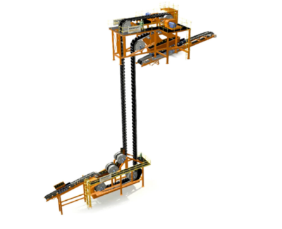
The background information on vertical conveying was provided to me by FKC-Lake Shore, a construction contractor that installs these systems.  FKC itself does not fabricate the conveyor hardware.  A link to their website is here.
The head station and tail station assemblies are installed at the top and bottom of a shaft.  The conveyor belt simply hangs in the shaft between these two points.  There is no need for internal guides or hardware down the shaft.   The conveyor belting relies on embedded steel cables for tensile strength and pockets (or cells) to carry the material.
The Pocketlift conveyor system is based on the Flexowell technology.  This has been advanced for deep underground applications with a theoretical lift height of 700 metres in one stage.   The power transfer is achieved by two steel cord belts that are connected with rigid cross bars. The ore is fed into rubber pockets, which are bolted onto the cross bars.    The standard Pocketlift can reaches capacities up to 1,500 m3/h and lift heights up to 700 m, while new generations of the technology may achieve capacities up to 4,000 m3/h.
The FLEXOWELL®-conveyor system is capable of running both horizontally and vertically, or any angle in between.  These conveyors consist of FLEXOWELL®-conveyor belts comprised of 3 components: (i) Cross-rigid belt with steel cord reinforcement; (ii) Corrugated rubber sidewalls; (iii) transverse cleats to prevent material from sliding backwards.   They can handle lump sizes varying from powdery material up to 400 mm (16 inch). Material can be raised over 500 metres with reported capacities up to 6,000 tph.


The benefits of vertical conveying

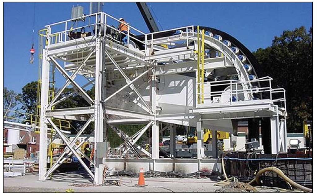
Vendors have evaluated the use of vertical conveying against the use of a conventional vertical shaft hoisting.    They report the economic benefits for vertical conveying will be in both capital and operating costs.
Reduced initial capital cost due to:
  • Smaller shaft excavation diameter,
  • Reduced cost of structural supports vs a typical shaft headframe,
  • Structural supports are necessary only in the loading and unloading zones and no support structures in the shaft itself since the belt hangs free.
Lower operating costs due to:
  • Significantly reduced power consumption and peak power demand,
  • Lower overall maintenance costs,
  • No shaft inspections required,
  • The belt is replaced every 8 – 10 years.

Conclusion

I consider vertical conveying as another innovation in the mining industry. There may be significant energy and cost benefits associated with it when compared to conventional shaft hoisting or truck haulage up a decline.
With raise boring, one can develop relatively low cost shafts for the vertical conveyor.  Hardware installation would be required only at the top and bottom of the shaft, not inside it.
The vendors indicate the conveying system should be able to achieve heights of 700 metres.  This may facilitate the use of internal shafts (winzes) to hoist ore from even greater depths in an expanding underground mine. It may be worth a look at your mine.
As stated earlier, I have no personal experience with vertical conveying. Undoubtedly there may be some negative issues associated with the system that I am currently unaware of.
I would appreciate anyone sharing their experience with these conveyors either in a civil application or a mining environment.   I will gladly update this blog article with additional observations or comments.
Update: for those interested in open pit applications for high angle conveyors, here is a recent article.  This is a 37 degree angle 3,000 tph sandwich belt, which is different than the vertical conveyors discussed above.
Note: You can sign up for the KJK mailing list to get notified when new blogs are posted.   Follow me on Twitter at @KJKLtd for updates and insights.
Share

Underground Feasibility Forecasts vs Actuals

underground costing
I recently attended a CIM Management and Economics Society presentation here in Toronto discussing the differences between actual underground production versus the forecast used in the feasibility study. The presenter was Paul Tim Whillans from Vancouver Canada.
His topic is interesting and relevant to today’s mining industry.  Paul raised many thoughtful points supported by data. He gave me permission to share his information.
The abstract for his paper is inerted below.  The paper can be downloaded at this LINK and here are the presentation slides.

ABSTRACT

An underground mining study that is done in accordance with NI43-101, JORC or similar reporting code is generally assumed by the public to be representative, independent and impartial. However, it has been well documented by academics and professionals in our industry that there is a sharp difference between the forecasts presented in these underground studies and the actual costs when a mine is put into production.
For underground mines, the risks associated with obtaining representative information are much greater than for surface mining and the cost of accessing underground ore is also proportionally much greater. There is a pressing need to align expectations, by improving the accuracy of projections. This will result in reduced risk to mining companies and investors and provide more reliable information to government agencies, the public, and more importantly, the communities in which the proposed mine will operate.
The objective of this article and an article currently being written titled “Mining Dilution and Mineral Losses” is to:
– Discuss the dynamics of intention that lead to over-optimism;
– Provide simple tools to identify which studies are likely to be more closely aligned with reality;
– Identify some specific points where underground mining studies are generally weak;
– Discuss practices currently in use in our industry that lead to a composite or aggregate effect of over optimism;
– Describe the effects of overly optimistic studies;
– Outline specific changes that are necessary to overcome these challenges; and
– Stimulate discussion and awareness that will lead to better standards.”

Conclusion

I agree with many of the points raised by Paul in his study. The mining industry has some credibility issues based on recent performance and therefore understanding the causes and then repairing that credibility will be important for the future.
Credibility ultimately impacts on shareholder returns, government returns, local community benefits, and worker health and safety; so having a well designed mine will realize benefits for many parties.
If you need more information Paul’s website is at http://www.whillansminestudies.com/
Note: You can sign up for the KJK mailing list to get notified when new blogs are posted.
Share