Remote Sensing of Ore Grades

mining automation
Update:  This blog was originally written in March 2016 and has been updated Jan 2019. 
The mining industry must continually find ways to improve and modernize. The most likely avenue for improvement will be using new technologies as they become available.
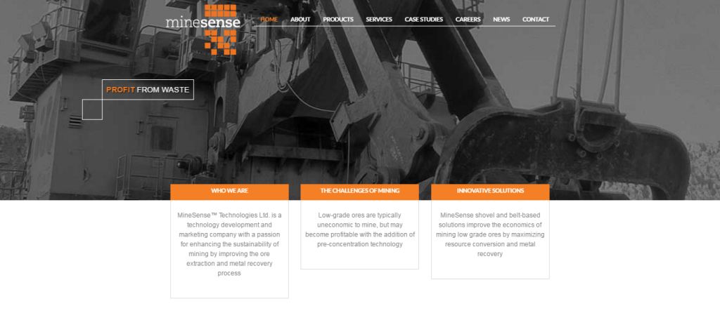
One of the players on the scene is a start-up company called “MineSense Technologies Ltd.”  They are a British Columbia company looking to improve ore extraction and recovery processes based on the sensing and sorting of low-grade ore. They hope their technology will improve mine economics by reducing the consumption of energy, water, and reagents.

Minesense

Having first written about this in 2016, its still not entirely clear to me how developed their technology is in 2019. Thus far they appear to be secretive with respect to their testing and performance results.  Certainly they are able to raise financing to keep them going.

Sensors are the answer

It appears MineSense is relying on a combination of ground-penetrating sensors with other technology in order to measure and report the grade of ore in real time.
Existing ore sorting technologies seem to focus on distinguishing mineralized material from gangue, but MineSense seems to be targeting using actual ore grades as the defining factor.
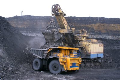
They hope to be able to eventually integrate their technology into equipment such as shovels, scooptrams, conveyors, feeders, and transfer chutes.
Their proprietary technology is based on High Frequency Electromagnetic Spectrometry and High Speed X-Ray Fluorescence sensors. Reportedly these can deliver better sensitivity and operate at high speeds. They plan to develop two distinct product lines; shovel-based systems; and conveyor belt-based systems.

ShovelSense

Their ShovelSense system would be a real-time mineral telemetry and decision system and used for measurement of ore quality while material is being scooped into the dipper, then reporting the ore quality and type to the grade control/ore routing system, and then enabling real-time online ore/waste dispatch decisions. Additional features may include tramp metal and missing tooth detection.  Sounds like a good idea, albeit some practical operating issues will need to be overcome.

BeltSense

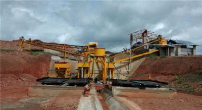
Their belt conveyor systems (BeltSense) will use high-speed multi-channel sensing to characterize conveyed ore and waste in real time, allowing grades and tonnages to be reported and allowing ore to be diverted to correct destinations based on the sensor responses.
MineSense say that pilot units are operating at 20 tph and systems of up to 2000 tph are in the development stages.
Ore sorting has been around for a long time, with companies like Tomra, but possibly the MineSense technical approach will be different.

Conclusion

The bottom line is that we should all keep an eye on the continued development of this technology, especially as MineSense completes larger field trials.  Hopefully they will soon share results with industry since it will be critical for operators to see more actual case study data on their website.
I recognize that developing new technology will have its successes and failures. Setbacks should not be viewed as failure since innovation takes time. Hopefully after fine tuning their technology they can advance to the commercialization stage.
Note: If you would like to get notified when new blogs are posted, then sign up on the KJK mailing list on the website.  Otherwise I post notices on LinkedIn, so follow me at: https://www.linkedin.com/in/kenkuchling/.
Share

Higher Metal Prices – Should Miners Lower the Cut-Off Grade?

When metals prices are high, we are generally told that we should lower the cutoff grade. Our cutoff grade versus metal price formula tells us this is the correct thing do. Our grade-tonnage curve reaffirms this since we will now have more metal in the mineral reserve.

But is lowering the cutoff grade the right thing?

Books have been written on the subject of cutoff grades where readers can get all kinds of detailed logic and calculations using Greek symbols (F = δV* − dV*/dT). Here is one well known book by Ken Lane, available on Amazon HERE.
Recently we have seen a trend of higher cash costs at operating mines when commodity prices are high. Why is this?
It may be due to higher cost operating inputs due to increasing labour rates or supplies. It may also be partly due to the lowering of cutoff grades.  This lowers the head grade, which then requires more tonnes to be milled to produce the same quantity of metal.
A mining construction manager once said to me that he never understood us mining guys who lower the cutoff grade when gold prices increase. His concern was that since the plant throughput rate is fixed, when gold prices are high we suddenly decide to lower the head grade and produce fewer and higher cost ounces of gold.

Do the opposite

His point was that we should do the opposite.  When prices are high, we should produce more ounces of gold, not fewer. In essence, periods when supply is low (or demand is high) may not be the right time to further cut  supply by lowering head grades.
Now this is the point where the grade-tonnage curve comes into play.
Certainly one can lower the cutoff grade, lower the head grade and produce fewer ounces of gold.  The upside being an extension in the mine life.  A company can report more ounces in reserves and perhaps the overall image of the company looks better (if it is being valued on reserves).   To read more about the value of grade-tonnage curves, you check out this blog post “Grade-Tonnage Curves – Worthy of a Good Look.

What if metal prices drop back?

The problem is that there is no guarantee that metal prices will remain where they are and the new lower cutoff grade will remain where it is. If the metal prices drop back down, the cutoff grade will be increased and the mineral reserve will revert back to where it was. All that was really done was accept a year of lower metal production for no real long term benefit.
This trade-off  contrasts a short term vision (i.e. maximizing annual production) against a long term vision (i.e. extending mineral reserves).

Conclusion

The bottom line is that there is no simple answer on what to do with the cutoff grades.  Hence there is a need to write books about it.
Different companies have different corporate objectives and each mining project will be unique with regards to the impacts of cutoff grade changes on the orebody.
I would like to caution that one should be mindful when plugging in new metal prices, and then running off to the mine operations department with the new cutoff grade. One should fully understand both the long term and short term impacts of that decision.
In another blog post on the cutoff grade issue, I discuss whether in poly-metallic deposits the cutoff should be based on metal equivalent or block NSR value.  Neither approach is perfect, but I prefer the NSR option.  You can read that post at “Metal Equivalent Grade versus NSR for Poly-Metallics“.


Note: If you would like to get notified when new blogs are posted, then sign up on the KJK mailing list on the website.  Otherwise I post notices on LinkedIn, so follow me at: https://www.linkedin.com/in/kenkuchling/.
Share

Using Pumped Sand to Build Mine Roads

geogrids
Several years ago I did some geotechnical consulting for BHP’s bauxite mining projects along the north coast of Suriname.  The mines were located in swampy terrain, underlain by very soft clays.   The picture below shows the typical landscape when crossing one of the swamps.  Haul roads were needed to access the small satellite bauxite pits, which were spread apart several kilometres.   The high ground in the background is one such bauxite deposit.
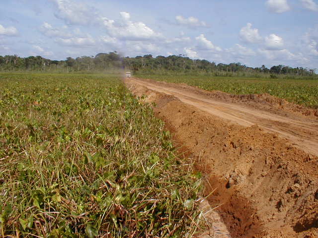
Sand road across swamp

Suriname swamp road for mine

Unfortunately where haul road construction was concerned, there were no nearby gravel pits or road aggregate supplies.  However there were significant amounts of fine sand on the high ground “islands” in the swamp.  Road building mainly relied on end dumping truck loads of sand, allowing it to settle and sink into the swamp.  Then continue adding more and more sand until the settling process stopped.  This resulted in high cost roads and very slow progress in construction.  Periodic rainfalls, daily during wet season, would cause havoc with the trafficability on the fine sands.

Swamp vegetation to the rescue
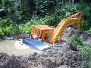
backhoe on soft clays
How soft were the swamps clays?  See the photo to the right.
Where there was significant swamp vegetation (like in the photo above), it would be buried by the fill, helping to form a mat.  This supported the road fill and minimized the sand losses into the sub-grade.  However in some parts of the swamp the vegetation was minimal and therefore sand settlement losses could be high.
Geotextiles were applied in some areas, using a geogrid.  These were successful although large amounts of sand were still required as the entire road would compress the underlying clay.
Once a road was built, the next issue was the trafficability on the fine sand surface, especially after rains.  The sand would rut and require constant grading and repair.
Final road capping would consist of hard laterite when available.  Laterite is a high iron off-grade bauxite that could be compacted to form a hard surface but would still degrade and get slippery when wet.
If coarse aggregate had been available locally, road performance would have been much better.  However we had to work with what was available.

Geo-cells would have helped
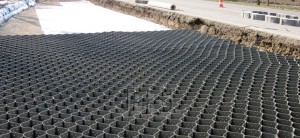
Geocell

A few years later I saw a video about a geo-cell solution for building roads with sand only.   The website is The PRS-Neoweb™ Cellular Confinement System (www.prs-med.com).  I think there are other similar geotextiles available but this is one that is well described on their website.   Sand is placed into the geoweb, which eventually forms a stiffer layer.  I assume that one could place the sand using mobile equipment or by hydraulically pumping coarse sand as a slurry.
In hindsight, I would have liked the opportunity to test the geo-cell system in the swamps of Suriname.  Potentially it would have been a good solution to prevent both sand losses and to create a more trafficable surface.
I’m not certain if the best location for the geo-cell would have been along the sub-base of the road to support the sand load or near the surface to help create a more trafficable surface. Maybe it would have been beneficial in both situations.
Building a road over a swamp in Suriname is somewhat similar to building a road out onto a tailings pond.  Possibly the geo-cells would have application there too.

Use Hydraulic Sand

Another large earthwork project we undertook in Suriname was building a dragline walkway across a swamp.   The walkway was 4 km long, 30 m wide and about 2 m thick. That required a lot of fill.   This walkway was built using hydraulic sand.  Boskalis, a Dutch dredging company, collect sand from the bottom of the Suriname River, barged it to a staging site about 5 km from the walkway, and then pumped the sand to the construction site.
The hydraulic sand was discharged between two bunds where it quickly settled out.  It was somewhat similar to a tailings disposal operation.  Placing the sand using this approach was low cost and didn’t require trucks driving out onto the swamp.  It also advanced the road with a very shallow front face, avoiding slumping failures or mudwaves ahead of the advance.  A few softer sections of the walkway route also incorporated geotextiles.
Engineering teams need to look at options since different procedures may be required when building roads over swamps due to the unstable conditions one may encounter.

Conclusion

Geotextiles have many applications in the mining industry.  There can be significant up-front costs to purchase and install them but don’t let that scare you away.   The savings may been seen down the line. They are definitely worth a look.
The big issue in Suriname were clays, both under the roads and in the overburden above the bauxite deposits.   Clays can have many forms, all of which can be problematic to deal with.  I have written another blog post about my experiences with the different types of clay and how they may behave.  If interested, check it out at “Clays and Mining – Friends or Foes?
Note: You can sign up for the KJK mailing list to get notified when new blogs are posted. Follow me on Twitter at @KJKLtd for updates and other mining posts.
Share

Potash Ore Grades – Check the Units

KCl vs K2O
Having worked with the potash industry for many years, I have reviewed numerous geological reports for projects in Canada, Asia, Russia, and Africa.  One of the curious things that I have seen is the reporting of resource  grades in two different units; either as potassium oxide (K2O) or potassium chloride (KCl).

Is it K2O or KCl ?

Standard practice in the Saskatchewan industry is reporting ore grades using K2O units, with typical head grades in the range of 25% K2O.  Many of the international projects, but not all, have decided to use the KCl units. Therefore when comparing potash resource grades between deposits, one must be vigilant for the units used since there is a significant difference.
The conversion from K2O to KCl is based on the formula K2O = 0.6317 x KCl.   So a grade of 25% K20 is equal to 25/0.6317 = 39.6% KCl.  The KCl grade value is significantly higher.  The unit issue is relevant with low grade deposits, were an actual grade of 15% K2O may be reported as 23.7% KCl.  One might see the ore grade in KCl and assume it is comparable to Saskatchewan potash grades, when in reality they are quite different.

Concentration Ratio is the Key

When looking at different potash projects, particularly those involving underground mining, a key economic factor is the concentration ratio.  This ratio represents the tonnes of potash ore needed to produce a tonne of final saleable product.
Typically the final potash product has a grade of 60% K2O.  Therefore a potash ore with a grade of 25% K2O would have a concentration ratio of about 2.4:1 (60%/25%).  This means that 2.4 tonnes of potash must be processed to produce 1 tonne of product (ignoring the process recovery factor).   For a lower grade ore with a head grade of say 15% K2O, the concentration ratio is 4:1 (60%/15%).

potash mining

This gives a rough sense for the comparable operation size required to meet the same final product production levels.  This also gives a indication for the relative amounts of salt tailings requiring disposal.  Low grade ore can generate significant quantities of tailings, the disposal of which is becoming a larger permitting issue.
In the past gold grades have been reported as “oz/ton” or currently as “g/t”, but most geological reports today are consistent with “g/t”.  Sometimes US based gold projects may use “oz/ton” however the magnitude in reported grades are fairly obvious between grams and ounces.  That isn’t the case with potash grades.
The bottom line is that potash is one commodity that will use different units when reporting ore grades.  Investors and reviewers must be aware of which units are being used.
If you are into potash mining, I have written a couple of blog posts about my brief, but interesting, time working at a potash mine in Saskatchewan.   This was early in my career and I had roles that included mine engineer, chief mine engineer and production foreman.  Each of these roles gave me a different perspective about a mining operation. In this two part blog, I share some stories relating to the uniqueness of potash mining.   If interested, here is the link “Stories from 3000 Feet Down – Part 1“.


Note: If you would like to get notified when new blogs are posted, then sign up on the KJK mailing list on the website.  Otherwise I post notices on LinkedIn, so follow me at: https://www.linkedin.com/in/kenkuchling/.


Share

Directional Drilling Open Pit Dewatering Wells – Great Idea

open pit dewatering
I read an interesting article in the Mining Magazine May 2015 edition called “Top 10 Technologies”.  One of the new technologies that jumped out at me is the capability to directionally drill open pit dewatering wells.   This is an oil field technology from Schlumberger Water Services that was now going to be applied to mining.
One of my past roles was as a mine engineer on the Diavik diamond mine team. Pit geotechnical and hydrogeology were under my domain during project design and permitting from 1997 to 2000.
The granitic rock mass was geotechnically very competent with a limited amount of jointing and fracturing.  The pits were going to be located within a lake bed.
It was anticipated that groundwater seepage coming from a partly permafrost pit wall could create a host of operational problems in winter. Most of the groundwater flows were predicted to be along a few major structures or along single open joints.
Generally these major structures were near vertical, which created a problem when trying to intercept them with vertically drilled depressurization wells.  Either you hit one or you didn’t.

The use of directional drilling of pumping wells is a great innovation

Directional drilling of dewatering wells gives the opportunity to angle a pumping well to an orientation that allows the well bore to cut across vertical structures rather than paralleling them.   In addition, one could drill pumping wells near the pit crest targeting towards the ultimate pit bottom.  This may help improve drainage near the operating benches as the pit deepens and could eliminate the need to install inpit pumping wells if water becomes a problem.
Some open pits have constructed underground drainage galleries around the pit circumference to help intercept deep groundwater seepage.  Possibly directionally drilling aligned parallel to the pit wall can replace such high cost drainage galleries.
The bottom line is that the directional drilling innovation makes a lot of sense and mine operators should take a look at it.  It might help improve their pit dewatering systems.
If anyone has experience with directionally drilled dewatering wells, please let us know.
The hydrogeology at Diavik was unique in that the ground consisted of both permafrost and unfrozen ground.  It was likely that unfrozen ground would eventually form permafrost over time once exposed to the cold winter climate.  To read more about the hydrogeology at Diavik, check out this link “Hydrogeology At Diavik – Its Complicated“.
The entire blog post library can be found at this LINK with topics ranging from geotechnical, financial modelling, and junior mining investing.
Note: If you would like to get notified when new blogs are posted, then sign up on the KJK mailing list on the website.   
Share

Pit Wall Angles and Bench Widths – How Do They Relate?

open pit slopes
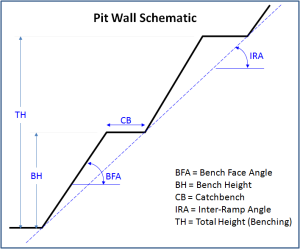
The wall of an open pit wall will consist of a series of stacked benches.  Geotechnical engineers will normally provide the pit slope design criteria based on the inter-ramp angle (“IRA”) for various sectors around the pit.  The IRA represents the toe-to-toe slope angle, as shown in the diagram below.

Pit Slope Image for post

The inter-ramp angle can be created in many ways, depending on the bench height (“BH”), bench face angle, and the catch bench or berm width.  Different combinations of these can be used to develop the same inter-ramp angle.
Typically the bench face angle (“BFA”) will be dictated by the rock strength, the structural fabric, and whether controlled blasting is used (minimizing damage to the walls).   The BFA may vary around the pit or in different rock types, but it typically is in the range of 60° to 75°.

Open Pit Slope

The catch bench (“CB”) or berm is used to catch spalling rock and prevent it from rolling down the pit wall,  creating a safety hazard.
A rule of thumb is that the catch bench width should be according to the formula 4.5m + 0.2H, where H is the height of the bench.   This means the recommended catch bench width for a 5m high bench should be about 5.5m; for a 10m high bench it should be 6.5m; and for 15m high bench it should be 7.5 metres.
Double benching (or triple benching) is used where the inter-ramp slopes angles are steep enough that single benching would result in an overly flatten slope.
For example if the inter-ramp slope is 50° and the BFA is 70°, then the corresponding calculated catch bench width for a 5m high bench would be 2.4 metres.  However such a small catch bench would be ineffective in catching spalliing rock.
If one double benched (i.e. left a catch bench every 10m instead of every 5m), then the calculated catch bench width would be 4.8 metres.  If one triple benched (i.e. left a catch bench every 15m), then the recommended width would be 7.1 metres.  Hence triple benching would be suggested in this case, assuming the rock mass is of sufficient strength to sustain a 15m high face.
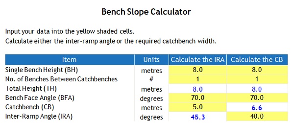
A simple interactive calculator (Bench Slope Calculator) has been prepared to show the relationship between all of these factors.  A screenshot of the calculator is shown below.  It allows one either to calculate the IRA given a set of bench height, BFA, and catch bench criteria; or calculate the catch bench width given the height, BFA, and IRA criteria.  The yellow shaded cells represent input cells.

Bench Slope Calculator Pic

Single Bench Height (BH):  this is the input height of a single operating bench.
No. of Benches between catch benches:   this is the input for single, double, or triple benching.
Total Height (TH):  this is the calculated total height (# of benches X single bench height)
Bench Face Angle (BFA):  this is the input bench face angle, in degrees
Catch bench (CB):  this is the width of the catch bench, either as an input or a calculated value.
Inter-Ramp Angle (IRA): this is the slope angle in degrees, either as a calculated value or an input.
When double or triple benching, sometimes a small 1-2m drill berm may be left between benches due to the inability of the drill to position itself against the pit wall.  The width of the drill berm can possibly be eliminated by drilling the entire double bench or using smaller drills.
Sometimes one may see the term “geotechnical berm”.   In some pit designs a large bench is introduced periodically, e.g. every 120m-180m in continous wall height, which acts as another measure to catch ravelling rock.

Conclusion

The bottom line is that the inter-ramp angle can be achieved in different ways depending on various components of the slope profile.  Safety is of the utmost importance and therefore the adequate sizing of the catch bench is important, as is the ability to access the benches and clean up the rubble buildup.  Double and triple benching maybe required in some circumstances to achieve the design wall angles yet maintain safety catch bench widths.
For those curious about how mine economics can be impacted by increasing the pit wall angle, a small study we did  indicated that going from 45 deg to 50 deg could reduce waste quantities by 15% This was equivalent to $50 million in savings.  To read more, follow this link.  “Steeper Pit Slopes Can Save Money“.
Note: If you would like to get notified when new blogs are posted, then sign up on the KJK mailing list on the website.  Follow us on Twitter at @KJKLtd for updates and insights.
Share