Gold Exploration Intercepts – Interesting or Not?

As a mining engineer, I am not usually called in to review a project that is still at the exploration stage. This is normally the domain of the geologist. However from time to time I have an interest in better understanding the potential of an early stage mining project. This could be on behalf of a client, for investing purposes, or just for personal curiosity.
At the exploration stage one only has drill interval data from news releases to examine. A resource estimate may still be unavailable.
The drill data can consist of long intervals of low grade or short intervals of high grade and everything in between. What does it all mean and what can it tell you?
The following describes an approach I use for examining early stage gold deposits. The logic can be expanded to other metals but would take more effort.
My focus is on gold because it has been the predominant deposit of interest over the last few years, and it is simpler to analyze quickly.

We All Like Scatter Plots

My approach relies on a scatter plot to visual examine the distribution of interval thicknesses and gold grades. Where these data points cluster or how they are distributed can provide some prediction on the overall economic potential of a project. Its not a guarantee, but only an indicator.
I try to group the analysis into potential open pit intervals (0 to 200 metres from surface) and potential underground (deeper than 200m) intervals. This is because a 20m wide interval grading 2.0 g/t is of economic interest when near surface, however of less interest if occurring at a 300m depth.
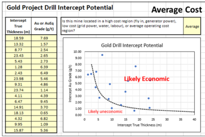
Using information from a news release, I create a two column Excel table of highlighted intervals and assay grades. The nice thing about using intervals is that the company has provided their view of the mineable widths.
If one is provided with raw 1-metre assay data you would have to make that decision, which can be a significant task. The company has already helped make those decisions.
Normally I tend to use the highlighted sub-intervals and not the main intervals since issues with grade smoothing can occur.
A large interval containing multiple high grade sub-intervals may see some grade smoothing.This happens if the grade between sub-intervals is very low grade or even waste. It takes a fair bit of effort to assess this for each drill hole, hence it is easier to work with the sub-intervals.
I have an online calculator (Drill Intercept Calculator) that lets you assess if grade smoothing is occurring.
When inputting the interval thickness, I prefer to use the true thickness and not the interval length. If the assay information does not specify true thicknesses, then I simply multiple the interval length by 0.70 to try to accommodate some possible difference in width. Its all subjective.
The assays can consist of Au (g/t) or AuEq (g/t) if more metals are present. If very high grades are encountered (greater than 10 g/t) I simply input 9.9 g/t into the Excel table so they fit onto my scatter plot. Extremely high grades can be sporadic and localized anyhow.
Finally I need to decide whether the project is located in a region of high operating cost, low cost or about average costs. High costs could be with a fly in/ fly out, camp operation, with diesel power, and seasonal access.
A low cost operation could be in temperate climate, with good access to local infrastructure, water, labour, and grid power. An average operation would be somewhere in between the two. Its just a gut feel.

Results

The following charts describe how it works, using randomly generated dummy assay data in this example.
In the Average cost scenario (left chart) the points are equally scattered both above and below the Likely Economic line. As one moves to a high-cost situation (middle chart) the curve moves upwards and more drill intervals now fall below the economic line.
This would give me an unfavorable impression of the project. The third graph is the Low-Cost scenario and one can see that more assays are now above the line. Hence the same project located in a different region would yield a different economic impression.
The economic boundaries (dashed lines) presented in the plots are based on my personal experience and biases. Other people may have different criteria to define what they would view as economic and uneconomic intervals.

Conclusion

There is not much that a layperson person can do with the multitude of exploration data provided in corporate news releases. However, by aggregating the data one can get a sense of where a gold project positions itself economically. The more data points available, the more that one can gather from the plot.
One should prepare separate plots for shallow and deep mineralization or for different zones and deposits on a property rather than aggregate everything together.
It may be possible to undertake a similar analysis with different commodities if one can summarize the assays into a single equivalent value or NSR dollar value. Unfortunately, exploration news releases don’t often include the poly-metallic interval equivalent grade or NSR value. Calculating these manually would add an extra step in the process, however it can be done.
If you want to try out the concept, I have posted the online spreadsheet to my website at the link Drill Intercept Potential where you can input Au exploration data of interest. Unfortunately, you cannot save your input data so it’s a one time event.   Anyone can do this – its not rocket science.
Let me know your thoughts, suggestions, or other ways to play with news release data.
If your project contains metals other than gold, then the rock (or ore) value will be based on the revenue from a combination of metals.   How to approach this in discussed in another blog post titled Ore Value Calculator – What’s My Ore Worth?

Great Bear Resources Example

Interesting the Great Bear Resources website allows one to download a data file with all their exploration intervals.  I have not seen another company provide this level of transparency.   I download their data file of over 1300 intervals and sub-divided them into major intervals and sub-intervals (more ore less).   The two plots below show the outcome.
The graph on the left is the sub-intervals showing that many points are above the “economic” line.  There are numerous data points along the top axis, indicating many sub-intervals at >10 g/t at widths ranging from 1 to 15 metres.  The graph on the right shows the major intervals.  While there are still many along the top axis, there are now more along the 40m width but at grades ranging from 1 g.t to 6 g/t.
One would surmise from these plots that overall there are many intervals above the line in the economic zone, showing the potential of the project.  It also shows that GBR have encountered many intervals likely sub-economic, but that’s the exploration game.

Great Bear Resources data

Examining polymetallic drill results in a similar manner isn’t as simple as this.   The mutiple metals of interest make the calaculations a bit more complex.   Another blog post discusses the approach I use for polymetallic, at this this link Polymetallic Drill Results – Interesting or Not?
Note: You can sign up for the KJK mailing list to get notified when new blogs are posted. Follow me on Twitter at @KJKLtd for updates and insights.
Share

Two Mining Innovations – Load Scanning & Vehicle Tracking

The mining industry is always on the lookout for new innovations as it strives to keep up with other industries.  In that light, periodically I like to highlight new technologies that I become aware of.   I’m trying to help spread the word  about them, which in turn may assist them in their on-going growth and development.
In this article I want to briefly describe two hardware / software companies that are working on technologies related to mine equipment productivity.    In no particular order, the two companies are Loadscan and SedimentIQ.  SedimentIQ is more of a startup than Loadscan which has a longer operating track record.
These technology companies are both targeting the open pit and underground markets, looking to provide simpler and less costly productivity solutions. Their technologies may be well suited for small to mid tier mines that cannot afford or don’t require the comprehensive Minestar type fleet management systems.
For the record, I get no fee or commission for promoting these companies; I just like what they are doing.

Loadscan

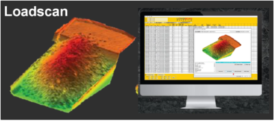
Loadscan has been around for a few years, but I only became aware of it recently.  It is a technology that allows the rapid assessment of the load being carried in truck.  It does not rely on the use of load cells or weigh scales to measure the payload.
Instead Loadscan uses a laser scanner and proprietary software to three dimensionally map the surface of the truck payload and then calculate its volume.  The results will indicate how consistent and optimal truck loading is volumetrically.   One can then calculate the payload tonnage by applying a bulk density.
The Loadscan technology will assess whether trucks are being over or under loaded, whether the loads are off-centre, or whether there is excess carryback on the return trip.
Successive truck payloads can be tracked manually or with RFID tags.   A cloud based database and web based dashboard are used to store the data and summarize it. The output can include an image of each individual load.
What is interesting about this technology is that it is simple to install in an operation.  It does not require retrofitting of a truck.
Results are immediate.  Loadscan provided an example where a message readout board can let the shovel operator immediately know how well each truck was loaded, resulting in improved education and better performance efficiency.
One can also assess how much better shovel bucket factors are in well blasted rock versus in blocky rock.
The Loadscan system is already in use in several mines globally.  The vendors can provide more technical  data if you need it.
Their website is https://www.loadscan.com/

SedimentIQ

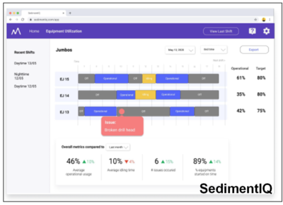
SedimentIQ is a new smartphone vehicle tracking platform that is trying to establish itself.  Their proposed technology makes use of a phone’s built-in GPS, Bluetooth, and accelerometer to track vehicle operation.  The phone’s sensor can measure vibrations produced by an operating truck or loader.
Vibration is a fingerprint of a vehicle’s activity.  Therefore using machine learning, the SedimentIQ app can produce an “activity score” that decides whether a machine is parked, idling, or performing productive work.  The phone is not connected to the machine diagnostics system, so its very easy to install, only needing a power source.
The system will be able to be used on any vehicle, including trucks, drills, loaders, graders, dozers, etc. The system has the capability to monitor equipment location and speed.
In an open pit environment it uses the phone’s GPS to monitor vehicle location. In an underground setting the phone reads inexpensive Bluetooth beacons mounted along the side walls to track location.
The app will identify delay and downtime based on equipment vibration levels.  The system currently requires no interaction with the operator, working in the background.  Hence it will not identify the cause of delay (i.e. blasting delay, breakdown, inter-equipment delay, etc).  I would expect that in the future they could add a feature for the operator to tag delay types on the touch screen.
The SedimentIQ software will aggregate the cycle time and delay information and upload it in real time to a cloud based database.  A web-based dashboard allows anyone with access to view the real time production data graphically or export it to Excel.
The SedimentIQ platform is less expensive than high end fleet management software.  Although it may not provide all the bells and whistles of the high end software, it may deliver just what you need to monitor productivity in your mining operation.  It relies on relatively inexpensive smart phones that are locked to the application.
I recall as a mining student doing time studies.  I rode the shift crew bus with pencil in hand, timing the travel  from the mine dry to the various shovels to measure start up times.  I recall sitting with a stopwatch timing shovel buckets and truck loading times.  Both of these tasks can be done for every shift, every truck by equipping the crew bus and mine trucks with the SedimentIQ tech.
The platform is currently being tested at a couple of trials mines and the founders are looking for more mines willing to adopt and further refine their technology.  Lets hope they can make a successful go of it.
The website is https://sedimentiq.com/.

Conclusion

Both of these innovative technologies can provide useful information to open pit and underground mine operations.  They are in the growth stage, looking for wider adoption.   Input from users, whether positive or negative, will assist them with on-going development and enhancements. Their websites obviously have more on what their technology offers, including presentations, white papers, and case studies.
It would be nice to meld these two technologies in some way to allow the SedimentIQ cycle times to also track payloads.
Check them out.  Try them out.


Note: You can sign up for the KJK mailing list to get notified when new blogs are posted.   Follow me on Twitter at @KJKLtd for updates and insights.
Share

O/P to U/G Cross-Over – Two Projects into One

Over the years I have been involved in numerous mining tradeoff studies. These could involve throughput rate selection, site selection, processing options, tailings disposal methods, and equipment sizing. These are all relatively straightforward analyses. However, in my view, one of the more technically interesting tradeoffs is the optimization of the open pit to underground crossover point.
The majority of mining projects tend to consist of either open pit only or underground only operations. However there are instances where the orebody is such that eventually the mine must transition from open pit to underground. Open pit stripping ratios can reach uneconomic levels hence the need for the change in direction.
The evaluation of the cross-over point is interesting because one is essentially trying to fit two different mining projects together.

Transitioning isn’t easy

There are several reasons why open pit and underground can be considered as two different projects within the same project.
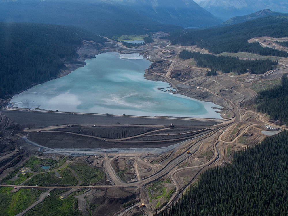
There is a tug of war between conflicting factors that can pull the cross-over point in one direction or the other. The following discussion will describe some of these factors.
The operating cut-off grade in an open pit mine (e.g. ~0.5 g/t Au) will be lower than that for the underground mine (~2-3 g/t Au). Hence the mineable ore zone configuration and continuity can be different for each. The mined head grades will be different, as well as the dilution and ore loss assumptions. The ore that the process plant will see can differ significantly between the two.
When ore tonnes are reallocated from open pit to underground, one will normally see an increased head grade, increased mining cost, and possibly a reduction in total metal recovered. How much these factors change for the reallocated ore will impact on the economics of the overall project and the decision being made.
A process plant designed for an open pit project may be too large for the subsequent underground project. For example a “small” 5,000 tpd open pit mill may have difficulty being kept at capacity by an underground mine. Ideally one would like to have some satellite open pits to help keep the plant at capacity. If these satellite deposits don’t exist, then a restricted plant throughput can occur. Perhaps there is a large ore stockpile created during the open pit phase that can be used to supplement underground ore feed. When in a restricted ore situation, it is possible to reduce plant operating hours or campaign the underground ore but that normally doesn’t help the overall economics.
Some investors (and companies) will view underground mines as having riskier tonnes from the perspective of defining mineable zones, dilution control, operating cost, and potential ore abandonment due to ground control issues. These risks must be considered when deciding whether to shift ore tonnes from the open pit to underground.
An underground mine that uses a backfilling method will be able to dispose of some tailings underground. Conversely moving towards a larger open pit will require a larger tailings pond, larger waste dumps and overall larger footprint. This helps make the case for underground mining, particularly where surface area is restricted or local communities are anti-open pit.

Another issue is whether the open pit and underground mines should operate sequentially or concurrently. There will need to be some degree of production overlap during the underground ramp up period. However the duration of this overlap is a subject of discussion. There are some safety issues in trying to mine beneath an operating open pit. Underground mine access could either be part way down the open pit or require an entirely separate access away from the pit.
Concurrent open pit and underground operations may impact upon the ability to backfill the open pit with either waste rock or tailings. Underground mining operations beneath a backfilled open pit may be a concern with respect to safety of the workers and ore lost in crown pillars used to separate the workings.
Open pit and underground operations will require different skill sets from the perspective of supervision, technical, and operations. Underground mining can be a highly specialized skill while open pit mining is similar to earthworks construction where skilled labour is more readily available globally. Do local people want to learn underground mining skills? Do management teams have the capability and desire to manage both these mining approaches at the same time?
In some instances if the open pit is pushed deep, the amount of underground resource remaining beneath the pit is limited. This could make the economics of the capital investment for underground development look unfavorable, resulting in the possible loss of that ore. Perhaps had the open pit been kept shallower, the investment in underground infrastructure may have been justifiable, leading to more total life-of-mine ore recovery.
The timing of the cross-over will also create another significant capital investment period. By selecting a smaller this underground investment is seen earlier in the project life. This would recreate some of the financing and execution risks the project just went through. Conversely increasing the open pit size would delay the underground mine and defer this investment and its mining risk.

Conclusion

As you can see from the foregoing discussion, there are a multitude of factors playing off one another when examining the open pit to underground cross-over point. It can be like trying to mesh two different projects together.
The general consensus seems to be to push the underground mine as far off into the future as possible.  Maximize initial production based on the low risk open open pit before transitioning.
One way some groups will simplify the transition is to declare that the underground operation will be a block cave. That way they can maintain an open pit style low cutoff grade and high production rate. Unfortunately not many deposits are amenable to block caving.  Extensive geotechnical investigations are required to determine if block caving is even applicable.
Optimization studies in general are often not well documented in 43-101 Technical Reports. In most mining studies some tradeoffs will have been done (or should have been done).  There might be only brief mention of them in the 43-101 report. I don’t see a real problem with this since a Technical Report is to describe a project study, not provide all the technical data that went into it. The downside of not presenting these tradeoffs is that they cannot be scrutinized (without having data room access).
One of the features of any optimization study is that one never really knows if you got it wrong. Once the decision is made and the project moves forward, rarely will someone ever remember or question basic design decisions made years earlier. The project is now what it is.


Note: You can sign up for the KJK mailing list to get notified when new blogs are posted. Follow me on Twitter at @KJKLtd for updates and insights.
Share

Are Engineers Too Pessimistic

Geological colleagues have often joked that engineers are a pessimistic lot; they are never technically satisfied. The engineers will fire back that geologists are an overly optimistic lot; every speck of mineralization makes them ecstatic. Together they make a great team since each cancels the other out.
In my opinion engineers are often pessimistic. This is mainly because they have been trained to be that way. Throughout my own engineering career I have been called upon many times to focus on the downsides, i.e. what can happen that we don’t want to happen.

It starts early and continues on

This pessimism training started early in my career while working as a geotechnical engineer. Geotechnical engineers were always looking at failure modes and the potential causes of failure when assessing factors of safety.
Slope failure could be due to the water table, excess pore pressures, seismic or blast vibrations, liquefaction, unknown weak layers, overly steepen slopes, or operating error. As part of our job we had to come up with our list of negatives and consider them all. The more pessimistic view you had, the better job you did.
This training continued through the other stages of a career. The focus on negatives continues in mine planning and costing.
For example, there are 8,760 hours in a year, but how many productive hours will each piece of equipment provide? There will delays due to weather conditions, planned maintenance, unplanned breakdowns, inter-equipment delays, operator efficiency, and other unforeseen events. The more pessimistic a view of equipment productivity, the larger the required fleet. Geotechnical engineers would call this the factor of safety.
In the more recent past, I have been involved in numerous due diligences. Some of these were done for major mining companies looking at acquisitions. Others were on behalf of JV partners, project financiers, and juniors looking at acquisitions.
When undertaking a due diligence, particularly for a major company or financier, we are not hired to tell them how great the project is. We are hired to look for fatal flaws, identify poorly based design assumptions or errors and omissions in the technical work. We are mainly looking for negatives or red flags.
Often we get asked to participate in a Risk Analysis or SWOT analysis (Strengths-Weaknesses-Opportunities-Threats) where we are tasked with identifying strengths and weaknesses in a project.
Typically at the end of these SWOT exercises, one will see many pages of project risks with few pages of opportunities.
The opportunities will usually consist of the following cliches (feel free to use them in your own risk session); metal prices may be higher than predicted; operating costs will be lower than estimated; dilution will be better than estimated; and grind size optimization will improve process recoveries.
The project’s risk list will be long and have a broad range. The longer the list of risks, the smarter the review team appears to be.

Investing isn’t easy

After decades of the training described above, it becomes a challenge for me to invest in junior miners. My skewed view of projects carries over into my investing approach, whereby I tend to see the negatives in a project fairly quickly. These may consist of overly optimistic design assumptions or key technical aspects not understood in sufficient depth.
Most 43-101 technical reports provide a lot of technical detail; however some of them will still leave me wanting more. Most times some red flags will appear when first reviewing these reports. Some of the red flags may be relatively inconsequential or can be mitigated. However the fact that they exist can create concern. I don’t know if management knows they exists or knows how they can mitigate them.
It has been my experience that digging in a data room or speaking with the engineering consultants can reveal issues not identifiable in a 43-101 report. Possibly some of these issues were mentioned or glossed over in the report, but you won’t understand the full extent of the issues until digging deeper.
43-101 reports generally tell you what was done, but not why it was done. The fact I cannot dig into the data room or speak with the technical experts is what has me on the fence. What facts might I be missing?
Statistics show that few deposits or advanced projects become real mines. However every advanced study will say that this will be an operating mine. Many projects have positive feasibility studies but these studies are still sitting on the shelf. Is the project owner a tough bargainer or do potential acquirers / financiers see something from their due diligence review that we are not aware of?   You don’t get to see these third party reviews unless you have access to the data room.
My hesitance in investing in some companies unfortunately can be penalizing. I may end up sitting on the sidelines while watching the rising stock price. Junior mining investors tend to be a positive bunch, when combined with good promotion can result in investors piling into a stock.
Possibly I would benefit by putting my negatives aside and instead ask whether anyone else sees these negatives. If they don’t, then it might be worth taking a chance, albeit making sure to bail out at the right time.
Often newsletter writers will recommend that you “Do your own due diligence”. Undertaking a deep dive in a company takes time. In addition I’m not sure one can even do a proper due diligence without accessing a data room or the consulting team. In my opinion speaking with the engineering consultants that did the study is the best way to figure things out. That’s one reason why “hostile” due diligences can be difficult, while “friendly” DD’s allow access to a lot more information.

Conclusion

Sometimes studies that I have been involved with have undergone third party due diligence. Most times one can predict ahead of time which issues will be raised in the review. One knows how their engineers are going to think and what they are going to highlight as concerns.
Most times the issue is something we couldn’t fully address given the level of study. We might have been forced to make best guess assumptions to move forward. The review engineers will have their opinions about what assumptions they would have used. Typically the common comment is that our assumption is too optimistic and their assumption would have been more conservative or realistic (in their view).
Ultimately if the roles were reversed and I were reviewing the project I may have had the same comments. After all, the third party reviewers aren’t being hired to say everything is perfect with a project.
The odd time one hears that our assumption was too pessimistic. You usually hear this comment when the reviewing consultant wants to do the next study for the client. They would be a much more optimistic and accommodating team.
To close off this rambling blog, the next time you feel that your engineers are too negative just remember that they are trained to be that way.  If you want more positivity, hang out with a geologist (or hire a new grad).


Note: You can sign up for the KJK mailing list to get notified when new blogs are posted. Follow me on Twitter at @KJKLtd for updates and insights.
Share

Vertical Conveyors Give Mining a Lift

There are not many things that are novel to me after having worked in the mining industry for almost 40 years.  However recently I came across a mining technology that I had heard very little about.  It’s actually not something new, but it has never been mentioned as a materials handling option on any project that I am aware of.
That innovative technology is vertical conveying. Not long ago I read about a vertical conveyor being used at the Fresnillo underground mine, hoisting 200 tph up from a depth of 400 metres and had a capital cost of $12.7 million.
I was aware of steep angle conveyors being used in process plants.  However they tended to be of limited height and have idlers and hardware along their entire length. Vertical conveyors are different from that.
After doing a bit of research, I discovered that vertical conveyors have been used since the 1970’s.  Their application was mainly in civil projects; for example in subway construction where one must elevate rock from the excavation level up to street level.   The mining industry is taking vertical conveyors to the next level.
I have never personally worked with vertical conveyors.  Therefore I am providing this discussion based on vendor information.  My goal is to create awareness to readers so that they might consider its application for their own projects.

How vertical conveying works

The background information on vertical conveying was provided to me by FKC-Lake Shore, a construction contractor that installs these systems.  FKC itself does not fabricate the conveyor hardware.  A link to their website is here.
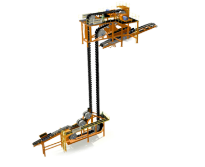
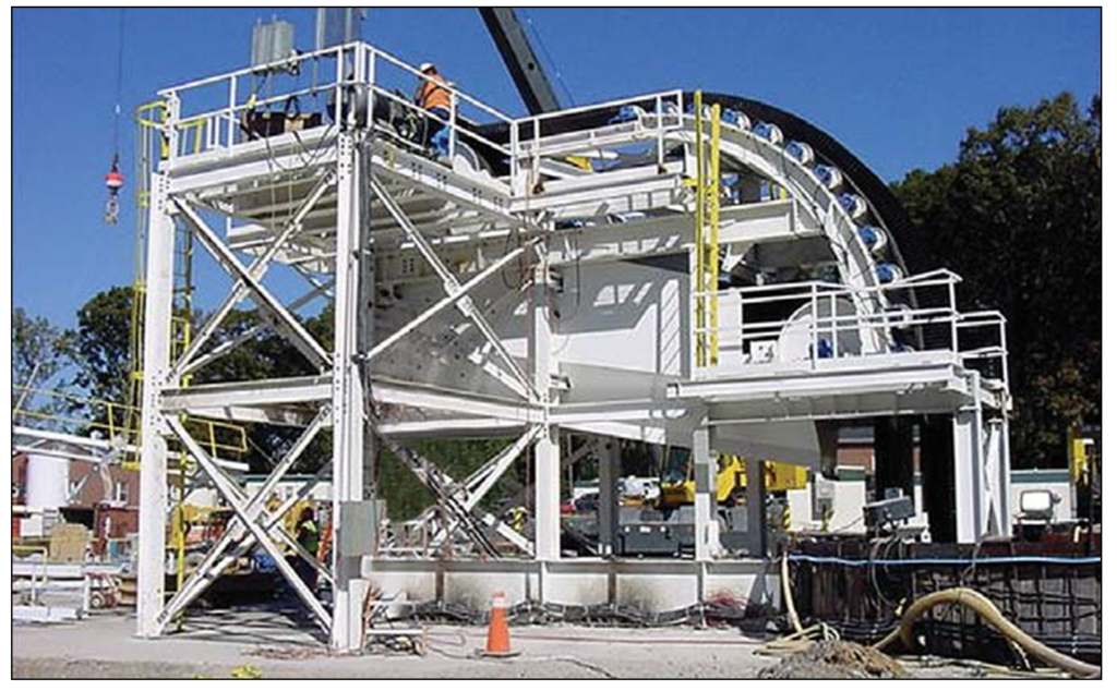
The head station and tail station assemblies are installed at the top and bottom of a shaft.  The conveyor belt simply hangs in the shaft between these two points.  There is no need for internal guides or hardware down the shaft.   The conveyor belting relies on embedded steel cables for tensile strength and pockets (or cells) to carry the material.
The Pocketlift conveyor system is based on the Flexowell technology.  This has been advanced for deep underground applications with a theoretical lift height of 700 metres in one stage.   The power transfer is achieved by two steel cord belts that are connected with rigid cross bars. The ore is fed into rubber pockets, which are bolted onto the cross bars.    The standard Pocketlift can reaches capacities up to 1,500 m3/h and lift heights up to 700 m, while new generations of the technology may achieve capacities up to 4,000 m3/h.
The FLEXOWELL®-conveyor system is capable of running both horizontally and vertically, or any angle in between.  These conveyors consist of FLEXOWELL®-conveyor belts comprised of 3 components: (i) Cross-rigid belt with steel cord reinforcement; (ii) Corrugated rubber sidewalls; (iii) transverse cleats to prevent material from sliding backwards.   They can handle lump sizes varying from powdery material up to 400 mm (16 inch). Material can be raised over 500 metres with reported capacities up to 6,000 tph.
 

The benefits of vertical conveying

Vendors have evaluated the use of vertical conveying against the use of a conventional vertical shaft hoisting.    They report the economic benefits for vertical conveying will be in both capital and operating costs.
Reduced initial capital cost due to:
  • Smaller shaft excavation diameter,
  • Reduced cost of structural supports vs a typical shaft headframe,
  • Structural supports are necessary only in the loading and unloading zones and no support structures in the shaft itself since the belt hangs free.
Lower operating costs due to:
  • Significantly reduced power consumption and peak power demand,
  • Lower overall maintenance costs,
  • No shaft inspections required,
  • The belt is replaced every 8 – 10 years.

Conclusion

I consider vertical conveying as another innovation in the mining industry. There may be significant energy and cost benefits associated with it when compared to conventional shaft hoisting or truck haulage up a decline.
With raise boring, one can develop relatively low cost shafts for the vertical conveyor.  Hardware installation would be required only at the top and bottom of the shaft, not inside it.
The vendors indicate the conveying system should be able to achieve heights of 700 metres.  This may facilitate the use of internal shafts (winzes) to hoist ore from even greater depths in an expanding underground mine. It may be worth a look at your mine.
As stated earlier, I have no personal experience with vertical conveying. Undoubtedly there may be some negative issues associated with the system that I am currently unaware of.
I would appreciate anyone sharing their experience with these conveyors either in a civil application or a mining environment.   I will gladly update this blog article with additional observations or comments.
Update: for those interested in open pit applications for high angle conveyors, here is a recent article.  This is a 37 degree angle 3,000 tph sandwich belt, which is different than the vertical conveyors discussed above.
Note: You can sign up for the KJK mailing list to get notified when new blogs are posted.   Follow me on Twitter at @KJKLtd for updates and insights.
Share

Heap Leach or CIL or Maybe Both

Typically gold mines consist of either a heap leach (HL) operation or a CIL type plant. There are a few projects that operate (or are considering) concurrent heap leach and CIL operations. Ultimately the mineral resource distribution determines if it makes economic sense to have both.  This blog discusses this concept based on past experience.
A CIL operation has higher capital and operating costs than a heap leach. However that higher cost is offset by achieving improved gold recovery, perhaps 20-30% higher. At higher gold prices or head grades, the economic benefit from improved CIL recovery can exceed the additional cost incurred to achieve that recovery.

Some background

Several years ago I was VP Engineering for a Vancouver based junior miner (Oromin Expl) who had a gold project in Senegal. We were in the doldrums of Stage 3 of the Lassonde Curve (read this blog to learn what I mean) having completed our advanced studies. Our timeline was as follows.
Initially in August 2009 we completed a Pre-Feasibility Study for a standalone CIL operation. Subsequently in June 2010 we completed a Feasibility Study. The technical aspects of Stage 2 were done and we were entering Stage 3. Now what do we do? Build or wait for a sale?
The property’s next door neighbor was the Teranga Sabodala operation. It made sense for Teranga to acquire our project to increase their long term reserves. It also made sense for a third party to acquire both of us. The Feasibility Study also made the economic case to go it alone and build a mine.
While waiting for various third-party due diligences to be completed, the company continue to do exploration drilling. There were still a lot of untested showings on the property and geologists need to stay busy.
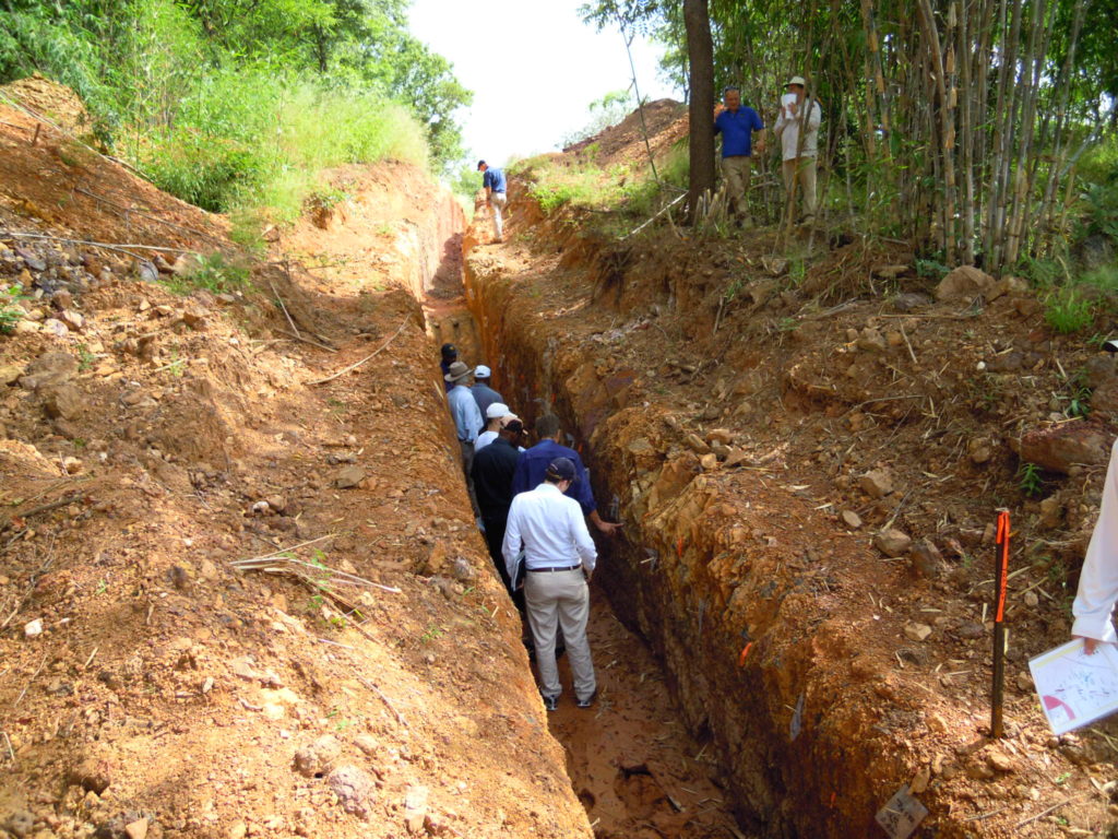
Two years later in 2013 we completed an update to the CIL Feasibility Study based on an updated resource model. Concurrently our geologists had identified seven lower grade deposits that were not considered in the Feasibility Study.
These deposits had gold grades in the range of 0.5 to 0.7 g/t compared to 2.0 g/t for the deposits in the CIL Feasibility Study. We therefore decided to also complete a Heap Leach PEA in 2013, looking solely on the lower grade deposits.
These HL deposits were 2-8 km from the proposed CIL plant so their ore could be shipped to the CIL plant if it made economic sense. Test work had indicated that heap leach recoveries could be in the range of 70% versus >90% with a CIL circuit. The gold price at that time was about $ 1,100/oz.
Ultimately our project was acquired by Teranga in the middle of 2013.

Where should the ore go?

With regards to the Heap Leach PEA, we did not wish to complicate the Feasibility Study by adding a new feed supply to that plant from mixed CIL/HL pits. The heap leach project was therefore considered as a separate satellite operation.
The assumption was that all of the low grade pit ore would go only to the heap leach facility. However, in the back of our minds we knew that perhaps higher grade portions of those deposits might warrant trucking to the CIL plant.
For internal purposes, we started to look at some destination trade-off analyses. We considered both hard (fresh rock) and soft ore (saprolite) separately. CIL operating costs associated with soft ore would be lower than for hard ore. Blasting wasn’t required and less grinding energy is needed. The CIL plant throughput rate could be 30-50% higher with soft ore than with hard ore, depending on the blend.
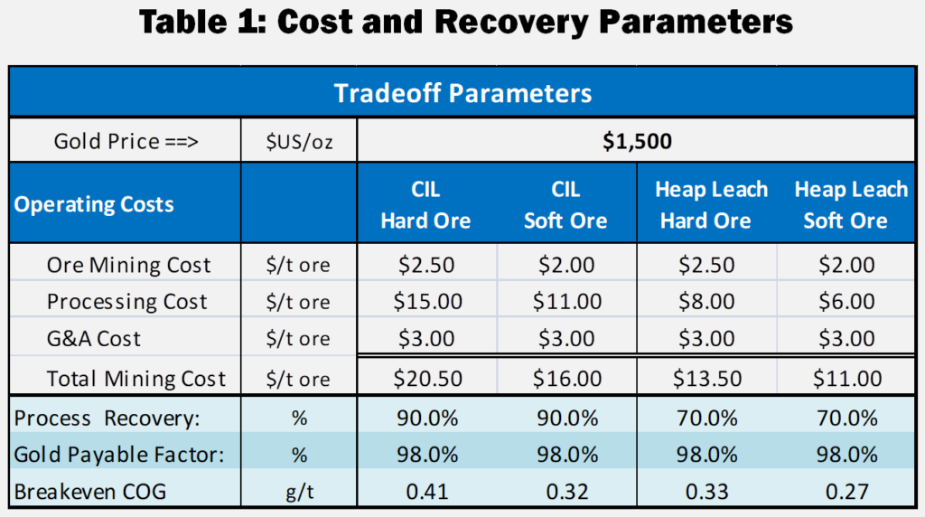
I have updated and simplified the trade-off analysis for this blog. Table 1 provides the costs and recoveries used herein, including increasing the gold price to $1500/oz.
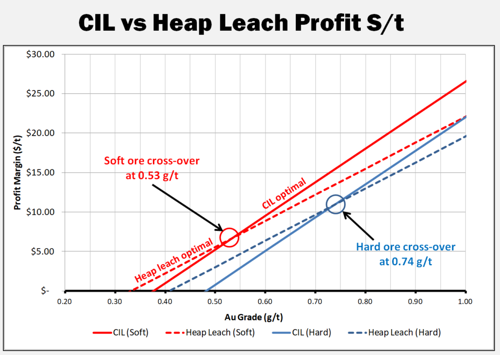
The graph shows the profit per tonne for CIL versus HL processing methods for different head grades.
The cross-over point is the head grade where profit is better for CIL than Heap Leach. For soft ore, this cross-over point is 0.53 g/t. For hard ore, this cross over point is at 0.74 g/t.
The cross-over point will be contingent on the gold price used, so a series of sensitivity analyses were run.
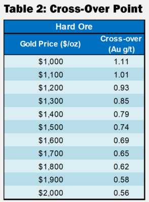
The typical result, for hard ore, is shown in Table 2. As the gold price increases, the HL to CIL cross-over grade decreases.
These cross-over points described in Table 2 are relevant only for the costs shown in Table 1 and will be different for each project.

Conclusion

It may make sense for some deposits to have both CIL and heap leach facilities. However one should first examine the trade-off for the CIL versus HL to determine the cross-over points.
Then confirm the size of the heap leach tonnage below that cross-over point. Don’t automatically assume that all lower grade ore is optimal for the heap leach.
If some of the lower grade deposits are further away from the CIL plant, the extra haul distance costs will tend to raise their cross-over point. Hence each satellite pit would have its own unique cross-over criteria and should be examined individually.
Since Teranga complete the takeover in mid 2013, we were never able to pursue these trade-offs any further.
Note: You can sign up for the KJK mailing list to get notified when new blogs are posted. Follow me on Twitter at @KJKLtd for updates and insights.
Share

Mining’s Lassonde Curve – A Wild Ride

Normally I don’t write about mining stock markets, preferring instead to focus on technical matters.  However I have seen some recent discussions on Twitter about stock price trends.  For every stock there are a wide range of price expectations.  Ultimately some of the expectations and realizations can be linked back to the Lassonde Curve.
The Lassonde Curve has been touted by many as a realistic representation of the life stages of a junior mining company.  The curve can sometimes be a roller coaster ride for company management.
Pierre Lassonde, was one of the founders of Franco-Nevada, the first gold royalty company. Thirty years ago he created his curve, that has now become a foundation in the junior mining business.  The Lassonde Curve outlines the company life stages, beginning at exploration and ending at production.  It shows the perceived value (i.e. stock value) that investors may assign at each life stage.
The stock price trend illustrated by the curve can, knowingly or unknowingly, impact on a company’s decision making process.  So in effect, there are some technical ramifications from it.
People may have differing opinions on what factors are driving the curve.   Take a look at it and decide for yourself. Typically people define the curve into four life stages, but I tend to view it in five stages.

Mining Company Stages 1 to 5

Stage 1 Climb

Stage 1 is the earliest stage, consisting of exploration.  This period generates rising anticipation from promotion and exciting press releases. The stock value climbs as the perceived value of the insitu geology increases.  Great Bear is an example of company currently in Stage 1 (as of June 2020), and appears to be in no hurry to exit from Stage 1.
Stage 2 is when the prospect moves into technical evaluation.  In other words, the engineers now climb aboard the ride.  This stage encompasses the PEA, PFS, and FS studies. Each of these can take months to complete, meantime new information releases may be lacking.
If the stock value declines, perhaps its because the engineers bring reality into the picture.  Investors may see that the project isn’t as easy or great as they anticipated during Stage 1.
Companies can also lose some presence in the market with no new news. Investors may begin looking at other companies that are still in Stage 1 and hence sell their shares.
Some companies may try to shorten Stage 2 and even skip over Stage 3 by going from a PEA directly into Stage 4 construction.
Stage 3 is the period when the studies have largely been completed and a production decision is pending.  At this time the company will be seeking strategic partners and project funding.  Permitting is also underway.  Unfortunately a lack of financing or poor permitting efforts will extend the time in Stage 3, which can extend for decades or even perpetuity. It’s easy to rattle off the names of companies sitting in Stage 3; for example Donlin Creek, Casino, KSM, and Galore Creek. It seems that once locked in a prolonged Stage 3, it can be difficult to get out of it.  Company promotion and marketing can be difficult.
Stage 4 begins when the financing is done and construction begins.  This is a sign that the project has been figured out, permits approved, and third-party due diligence found no fatal flaws.  The stock value may increase on this positive news, especially if construction is on time and on budget. Its even better news if it’s a period of rising commodity prices.
Stage 5 is the start-up and commercial production period, possibly nerve-racking for some investors. This is where the rubber hits the road. The stock price can fall if milled grades, operating costs, or production rates are not as expected.
Investors may need to decipher press releases to figure out if things are going well or not.  Some investors may now bail out at this time to companies in Stage 1 for greater upside (the 10 bagger).

Companies Staying front and center

Companies know that investors can move elsewhere at any time, so they will try to address the Stage 2 and Stage 3 doldrums in different ways.   They can:
  • Find new exploration prospects elsewhere while the engineering work is underway.
  • Undertake a series of optimization studies on the same project to keep up the news flow.
  • Continue step out drilling on the same property to expand resources and generate new excitement.
  • Have management appear regularly on podcasts, webinars, conferences, and keep promoting on LinkedIn, Twitter, and with newsletter writers.
Ideally one would like to stagger multiple prospects at different stages of the Curve. While this makes sense, it also takes a fair bit of funding to do it.   It also may bring criticism that the company is losing focus on their flagship project.  Generally if the stock price is improving, you don’t see this complaint.

Conclusion

In closing, I just wanted to present the Lassonde Curve for those who may not have seen it before. For those playing the junior stocks, it may help explain why their prices fluctuate for essentially the same project.  For some companies, the curve can be a wild ride.
Some corporate presentations will highlight the Lassonde Curve, particularly when they are rising in Stage 1.  You are less likely to see the curve presented when they are rolling along in Stages 2 or 3.
Some say the Curve relates to the de-risking of a project as it advances, with risks shifting from exploration related to development related.   That may be true, but I suggest the curve is simply based on investor perception and impatience.
The ability to promote oneself and stay relevant in the market plays a key role in defining the shape of a company’s curve.
As a final note, people looking at the Lassonde curve often focus on the rise and dip in the middle part. There is less focus on what happens on the far right side of the graph as it trends into the future. There is an often (but forgotten) dip there too.
Another interesting aspect of the junior mining industry is how the herd mentality and fear of missing out is standard operating policy.  Companies will rush into areas, acquire whatever ground they can, as long they can tout it as being a certain commodity project.   And its not only commodities that generate excitement; its also locations and technologies.  Read more at the blog post “Mining Fads and the Herd Mentality“.
The entire blog post library can be found at this LINK with topics ranging from geotechnical, financial modelling, and junior mining investing.
Note: You can sign up for the KJK mailing list to get notified when new blogs are posted.   Follow us on Twitter at @KJKLtd for updates and insights.
Share

Pre-Concentration – Maybe Good, Maybe Not

A while back I wrote a blog titled “Pre-Concentration – Savior or Not?”. That blog was touting the benefits of pre-concentration. More recently I attended a webinar where the presenter stated that the economics of pre-concentration may not necessarily be as good as we think they are.
My first thought was “this is blasphemy”. However upon further reflection I wondered if it’s true. To answer that question, I modified one of my old cashflow models from a Zn, Pb project using pre-concentration. I adjusted the model to enable running a trade-off, with and without pre-con by varying cost and recovery parameters.

Main input parameters

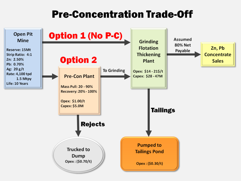
The trade-off model and some of the parameters are shown in the graphic below. The numbers used in the example are illustrative only, since I am mainly interested in seeing what factors have the greatest influence on the outcome.

The term “mass pull” is used to define the quantity of material that the pre-con plant pulls and sends to the grinding circuit. Unfortunately some metal may be lost with the pre-con rejects.  The main benefit of a pre-con plant is to allow the use of a smaller grinding/flotation circuit by scalping away waste. This will lower the grinding circuit capital cost, albeit slightly increase its unit operating cost.
Concentrate handling systems may not differ much between model options since roughly the same amount of final concentrate is (hopefully) generated.
Another one of the cost differences is tailings handling. The pre-con rejects likely must be trucked to a final disposal location while flotation tails can be pumped.  I assumed a low pumping cost, i.e to a nearby pit.
The pre-con plant doesn’t eliminate a tailings pond, but may make it smaller based on the mass pull factor. The most efficient pre-concentration plant from a tailings handling perspective is shown on the right.

The outcome

The findings of the trade-off surprised me a little bit.  There is an obvious link between pre-con mass pull and overall metal recovery. A high mass pull will increase metal recovery but also results in more tonnage sent to grinding. At some point a high mass pull will cause one to ask what’s the point of pre-con if you are still sending a high percentage of material to the grinding circuit.
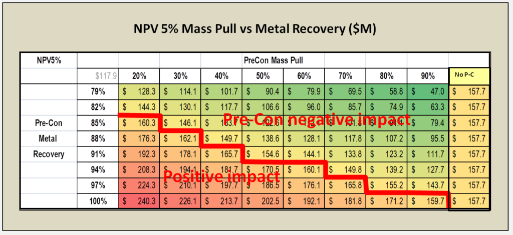
The table below presents the NPV for different mass pull and recovery combinations. The column on the far right represents the NPV for the base case without any pre-con plant. The lower left corner of the table shows the recovery and mass pull combinations where the NPV exceeds the base case. The upper right are the combinations with a reduction in NPV value.
The width of this range surprised me showing that the value generated by pre-con isn’t automatic.  The NPV table shown is unique to the input assumptions I used and will be different for every project.

The economic analysis of pre-concentration does not include the possible benefits related to reduced water and energy consumption. These may be important factors for social license and permitting purposes, even if unsupported by the economics.  Here’s an article from ThermoFisher on this “How Bulk Ore Sorting Can Reduce Water and Energy Consumption in Mining Operations“.

Conclusion

The objective of this analysis isn’t to demonstrate the NPV of pre-concentration. The objective is to show that pre-concentration might or might not make sense depending on a project’s unique parameters. The following are some suggestions:
1. Every project should at least take a cursory look at pre-concentration to see if it is viable. This should be done on all projects, even if it’s only a cursory mineralogical assessment level.
2. Make certain to verify that all ore types in the deposit are amenable to the same pre-concentration circuit. This means one needs to have a good understanding of the ore types that will be encountered.
3. Anytime one is doing a study using pre-concentration, one should also examine the economics without it. This helps to understand the  economic drivers and the risks. You can then decide whether it is worth adding another operating circuit in the process flowsheet that has its own cost and performance risk. The more processing components added to a flow sheet, the more overall plant availability may be effected.
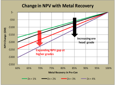
4. The head grade of the deposit also determines how economically risky pre-concentration might be. In higher grade ore bodies, the negative impact of any metal loss in pre-concentration may be offset by accepting higher cost for grinding (see chart on the right).
5. In my opinion, the best time to decide on pre-con would be at the PEA stage. Although the amount of testing data available may be limited, it may be sufficient to assess whether pre-con warrants further study.
6. Don’t fall in love with or over promote pre-concentration until you have run the economics. It can make it harder to retract the concept if the economics aren’t there.


Note: You can sign up for the KJK mailing list to get notified when new blogs are posted.
Follow us on Twitter at @KJKLtd for updates and insights.
Share

Climbing the Hill of Value With 1D Modelling

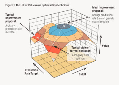
Recently I read some articles about the Hill of Value.  I’m not going into detail about it but the Hill of Value is a mine optimization approach that’s been around for a while.  Here is a link to an AusIMM article that describes it “The role of mine planning in high performance”.  For those interested, here is a another post about this subject “About the Hill of Value. Learning from Mistakes (II)“.
hill of value

(From AusIMM)

The basic premise is that an optimal mining project is based on a relationship between cut-off grade and production rate.  The standard breakeven or incremental cutoff grade we normally use may not be optimal for a project.
The image to the right (from the aforementioned AusIMM article) illustrates the peak in the NPV (i.e. the hill of value) on a vertical axis.
A project requires a considerable technical effort to properly evaluate the hill of value. Each iteration of a cutoff grade results in a new mine plan, new production schedule, and a new mining capex and opex estimate.
Each iteration of the plant throughput requires a different mine plan and plant size and the associated project capex and opex.   All of these iterations will generate a new cashflow model.
The effort to do that level of study thoroughly is quite significant.  Perhaps one day artificial intelligence will be able to generate these iterations quickly, but we are not at that stage yet.

Can we simplify it?

In previous blogs (here and here) I described a 1D cashflow model that I use to quickly evaluate projects.  The 1D approach does not rely on a production schedule, instead uses life-of-mine quantities and costs.  Given its simplicity, I was curious if the 1D model could be used to evaluate the hill of value.
I compiled some data to run several iterations for a hypothetical project, loosely based on a mining study I had on hand.  The critical inputs for such an analysis are the operating and capital cost ranges for different plant throughputs.
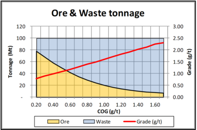
hill of valueI had a grade tonnage curve, including the tonnes of ore and waste, for a designed pit.  This data is shown graphically on the right.   Essentially the mineable reserve is 62 Mt @ 0.94 g/t Pd with a strip ratio of 0.6 at a breakeven cutoff grade of 0.35 g/t.   It’s a large tonnage, low strip ratio, and low grade deposit.  The total pit tonnage is 100 Mt of combined ore and waste.
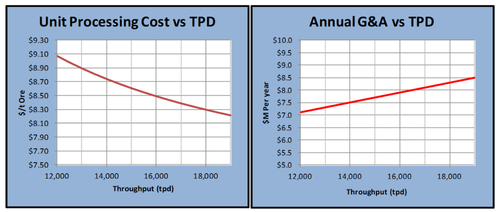
I estimated capital costs and operating costs for different production rates using escalation factors such as the rule of 0.6 and the 20% fixed – 80% variable basis.   It would be best to complete proper cost estimations but that is beyond the scope of this analysis. Factoring is the main option when there are no other options.
The charts below show the cost inputs used in the model.   Obviously each project would have its own set of unique cost curves.
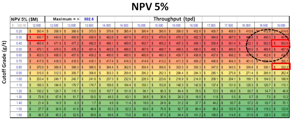
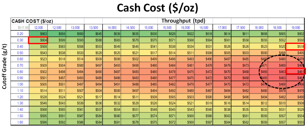
The 1D cashflow model was used to evaluate economics for a range of cutoff grades (from 0.20 g/t to 1.70 g/t) and production rates (12,000 tpd to 19,000 tpd).  The NPV sensitivity analysis was done using the Excel data table function.  This is one of my favorite and most useful Excel features.
A total of 225 cases were run (15 COG versus x 15 throughputs) for this example.

What are the results?

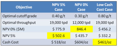
The results are shown below.  Interestingly the optimal plant size and cutoff grade varies depending on the economic objective selected.
The discounted NPV 5% analysis indicates an optimal plant with a high throughput (19,000 tpd ) using a low cutoff grade (0.40 g/t).  This would be expected due to the low grade nature of the orebody.  Economies of scale, low operating costs, high revenues, are desired.   Discounted models like revenue as quickly as possible; hence the high throughput rate.
The undiscounted NPV 0% analysis gave a different result.  Since the timing of revenue is less important, a smaller plant was optimal (12,000 tpd) albeit using a similar low cutoff grade near the breakeven cutoff.
If one targets a low cash cost as an economic objective, one gets a different optimal project.  This time a large plant with an elevated cutoff of 0.80 g/t was deemed optimal.
The Excel data table matrices for the three economic objectives are shown below.  The “hot spots” in each case are evident.

hill of value

hill of value

Conclusion

The Hill of Value is an interesting optimization concept to apply to a project.  In the example I have provided, the optimal project varies depending on what the financial objective is.  I don’t know if this would be the case with all projects, however I suspect so.
In this example, if one wants to be a low cash cost producer, one may have to sacrifice some NPV to do this.
If one wants to maximize discounted NPV, then a large plant with low opex would be the best alternative.
If one prefers a long mine life, say to take advantage of forecasted upticks in metal prices, then an undiscounted scenario might win out.
I would recommend that every project undergoes some sort of hill of value test, preferably with more engineering rigor. It helps you to  understand a projects strengths and weaknesses.  The simple 1D analysis can be used as a guide to help select what cases to look at more closely. Nobody wants to assess 225 alternatives in engineering detail.
In reality I don’t ever recall seeing a 43-101 report describing a project with the hill of value test. Let me know if you are aware of any, I’d be interested in sharing them.  Alternatively, if you have a project and would like me to test it on my simple hill of value let me know.
Note: You can sign up for the KJK mailing list to get notified when new blogs are posted.
Share

Simple Financial Models Can Really Help

A few years ago I posted an article about how I use a simple (one-dimensional) financial model to help me take a very quick look at mining projects. The link to that blog is here. I use this simple 1D model with clients that are looking at potential acquisitions or joint venture opportunities at early stages. In many instances the problem is that there is only a resource estimate but no engineering study or production schedule available.

By referring to my model as a 1D model, I imply that I don’t use a mine production schedule across the page like a conventional cashflow model would.
The 1D model simply uses life-of-mine reserves, life-of-mine revenues, operating costs, and capital costs. It’s essentially all done in a single column.  The 1D model also incorporates a very rudimentary tax calculation to ballpark an after-tax NPV.
The 1D model does not calculate payback period or IRR but focuses solely on NPV. NPV, for me, is the driver of the enterprise value of a project or a company. A project with a $100M NPV has that value regardless of whether the IRR is 15% or 30%.

How accurate is a 1D model?

One of the questions I have been asked is how valid is the 1D approach compared to the standard 2D cashflow model. In order to examine that, I have randomly selected several recent 43-101 studies and plugged their reserve and cost parameters into the 1D model.
It takes about 10 minutes to find the relevant data in the technical report and insert the numbers. Interestingly it is typically easy to find the data in reports authored by certain consultants. In other reports one must dig deeper to get the data and sometimes even can’t find it.
The results of the comparison are show in the scatter plots. The bottom x-axis is the 43-101 report NPV and the y-axis is the 1D model result. The 1:1 correlation line is shown on the plots.
There is surprisingly good agreement on both the discounted and undiscounted cases. Even the before and after tax cases look reasonably close.
Where the 1D model can run into difficulty is when a project has a production expansion after a few years. The 1D model logic assumes a uniform annual production rate for the life of mine reserve.
Another thing that hampers the 1D model is when a project uses low grade stockpiling to boost head grades early in the mine life. The 1D model assumes a uniform life-of-mine production reserve grade profile.
Nevertheless even with these limitations, the NPV results are reasonably representative. Staged plant expansions and high grading are usually modifications to an NPV and generally do not make or break a project.

Conclusion

My view is that the 1D cashflow model is an indicative tool only. It is quick and simple to use. It allows me to evaluate projects and test the NPV sensitivity to metal prices, head grades, process recovery, operating costs, etc. These are sensitivities that might not be described in the financial section of the 43-101 report.
This exercise involved comparing data from existing 43-101 reports. Obviously if your are taking a look at an early stage opportunity, you will need to define your own capital and operating cost inputs.
I prefer using a conventional cashflow model approach (i.e. 2D) when I can. However when working with limited technical data, it’s likely not worth the effort to create a complex cashflow model. For me, the 1D model can work just fine. Build one for yourself, if you need convincing.
In an upcoming blog I will examine the hill of value optimization approach with respect to the 1D model.
Note: You can sign up for the KJK mailing list to get notified when new blogs are posted.
Share