Articles tagged with: Environmental

Spying on Tailings Using Satellites

There have been recent heap leach pad failures in the Yukon and Turkey and tailings dam failures in Chile and the Philippines.  As a result I have been seeing more posts on LinkedIn about the application of satellite based InSAR deformation monitoring.  Prior to that I had never heard of InSAR, so thought a little bit of background study might be worthwhile.
The following are my observations on what InSAR is and where it may be going.  I am by no means an expert in this technology.  I am merely viewing it from the perspective of a mine design engineer.

What is InSAR

InSAR is satellite-based “Interferometric Synthetic Aperture Radar”.    It can measure the distance from a satellite to a ground feature.  With repeated imaging it is used to detect changes in distance and measure displacements to within 5-10 millimetre accuracy.  Hence it can be used as a potentially cost-effective slope monitoring tool, albeit it cannot be the only tool, as discussed later.
The relevant satellite images have been available for years.  Currently the availability of analytical software to interpret the satellite data is improving.   It can detect millimeter-scale displacements, however only in the line-of-sight (LOS) direction of the satellite.   Using two or more satellites in different orbits, displacements in horizontal and vertical directions can be defined.
An example of a satellite being used is the Sentinel-1, launched in mid-2015 by the European Space Agency. This satellite information is open-source data.  It will have a 6 to 12 day revisit cycle in many locations.
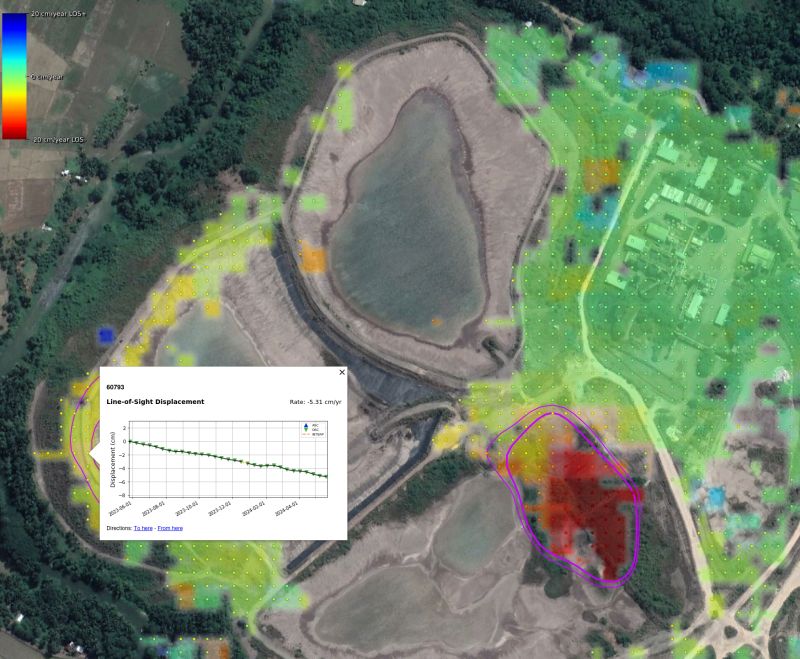
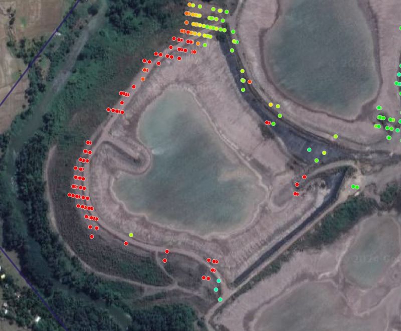
The results of an InSAR displacement survey are typically shown as a series of colored data points, typically coloured green for the stable points, trending to yellow and red for points that are moving.
This blog has some example images.

Some Limitations With InSAR

There are some limitations with InSAR, so it can only be part of a monitoring program.  These limitations are:
  • The displacement direction is only measured in the direction of the satellite.  Hence one may not know in which direction the movement is occurring.  The magnitude of displacement could be underestimated depending on the apparent angle of measurement.
  • The movement being measured could consist of vertical settlement due to material consolidation and may not be horizontal and related to impending failure.
  • The displacement magnitude measured on opposite sides of a facility may have different accuracy, depending on the slope orientation versus the line-of-sight.
  • Areas with heavy vegetation may be difficult to monitor
  • Areas with heavy or persistent cloud cover can be difficult to monitor.
  • Areas with snow cover will be difficult to monitor.
  • The satellite return period may be weekly or every two weeks, so one is not able to analyze daily movements if a situation is critical.  If the return visit day has cloud cover, there will be no new satellite data collected.
  • Areas with on-going construction or tailings deposition will lead to erroneous results.
  • Due to the line of sight, not all slope failure modes may be detectible (for example piping failure).
Regardless of these limitations, InSAR can still play a role in any monitoring program since it is able to monitor large areas quickly.   Consider it as a pre-screening tool, being aware that not all failure modes may be detectible with it.

Discussion

On LinkedIn, one can see numerous posts where independent experts are examining historical InSAR data for recent failures to see whether early movement should have been detected.  The results seem to be quite positive in that areas that have failed might have been red-flagged prior to failure.
There are also zones that showed critical displacements but have not failed.
Typically, there are four ways to monitor displacement in pit slopes, tailings dams, heap leach pads, and waste dumps.   They are:
  1. Insitu monitoring using embedded instruments, for example slope indicators, extensometers, and settlement gauges.  These instruments provide information on what is happening internally within a slope, where actual movement is occurring, and they can be used in warning alert systems.
  2. Surface monitoring using radar (ground based InSAR) systems and survey prisms.  These tools measure only surface movements in selected areas, can be monitored as frequently as needed on an automated basis, and integrated into warning alert systems.
  3. Drone or aerial surveys can be used to measure topography and monitor movements over large areas.   This method requires a data processing delay (not real time) to derive the movement information, but such surveys can be done as frequently as needed.
  4. InSAR from satellite can be used over very large regions to highlight areas with movement.  That should trigger the implementation of one or more of the other monitoring approaches (if not already in place).

Conclusion

A mining site consists of numerous constructed embankments and slopes of all types and heights.  Many of these slopes may be creeping and moving all the time – it’s a living beast.
The operator’s awareness about their site will be better the more monitoring tools they use.  This awareness is important given the critical role that slope stability plays.  We will see if InSAR technology achieves much wider adoption in the mining industry as a first phase of a stability monitoring programs.
Since InSAR monitoring is done from space, it does not require access to a property.  Hence it can be used by third parties or NGO’s to “spy” on facilities of concern anywhere.
Possibly over the next few years we will see independent donor-funded organizations monitoring tailings facilities around the globe.  They will be able to notify the public and mine operators “Hey, there is some movement on this mine site that needs to be addressed”.    An organization called World Mine Tailings Failures has started some discussions on this concept.   Check it out.
Finally, it is great for a mine site to collect a lot of displacement data, hopefully to forewarn of movement, displacement acceleration, and imminent failure.  However, this assumes that someone experienced is interpreting the data and its not just generating graphs for the file cabinet.   Perhaps AI can play a role here in the future, if the technical personnel to do this are lacking.
Note: You can sign up for the KJK mailing list to get notified when new blogs are posted. Follow me on Twitter at @KJKLtd for updates and other mining posts.   The entire blog post library can be found at https://kuchling.com/library/
Share

Filtered Tailings Testing Checklist

I have always been a big proponent of filtered (or dry stack) tailings over conventional tailings disposal. Several years ago I had written a blog (Fluid Tailings – Time to Kick The Habit?)  that this is the tailings disposal approach the mining industry should be moving toward.
Recently I have been seeing more mining studies proposing to use the dry stack approach. In some cases, they no longer even do the typical tailings trade-off study that look at different options. The decision is made upfront that dry stack is the preferred route due to its environmental acceptability and positive perceptions.
Recently I came across a nice document prepared by BHP and Rio Tinto titled “Filtered Stacked Tailings – A Guide for Study Managers (March 2024)”. I will refer to this document as “The Guide”. You should definitely get a copy of this Guide if your project is considering a dry stack operation. An information link is included at the end of this post.

A Guide for Study Managers

The Guide covers several topics, including tailings characterization; site closure concepts; filtered tailings stack design; material transport, stacking systems; and tailings dewatering methods. The Guide covers all the basics very well. The one area that jumped out at me is the tailings characterization and testing aspect.
Many assume that dry stack is simply filter, haul, dump, then walkaway. Its all very easy! However, in reality, the entire dry stack approach is complex.
One needs to be able to consistently dewater tailings from different ore types, then transport it under different climatic conditions, and then place and compact the tailings efficiently.
One also needs to be able to deal with plant upsets, when the filtered tailings don’t meet the optimal product specifications. So its not really that simple.
One of the chapters in the Guide details the different test work that should be done to understand the dry stack approach.  The list of tests is a lot longer than I had envisioned.  I previously knew some of the types of lab testing required, however the Guide outlines a very comprehensive list.
The Guide also categorizes the tests according to study stage, be it concept study, order of magnitude study, or Pre-Feasibility level. Interestingly, the concept study can rely mainly on published information. However, the more advanced mining studies require the lab testing of actual tailings material.

Testing Checklist

To help organize the complexity of testing, I have listed their suggested tests as to whether the test is related to material characterization, process characterization, or filtered product characterization. Each aspect serves a different purpose in understanding the workings of the filtered tailings approach. The engineer will decide at which study stage they wish to do each of the tests, or which of the them they actually need to do.
To keep the blog post brief, I am not describing the details for each test. Most geotechnical or process engineers will already be familiar with them, or anyone can search the web to learn more.

MATERIAL CHARACTERIZATION TESTS

  • Chemical composition Testing: using atomic absorption or spectroscopy, identify the elements within the tailings stream to highlight contaminants and potential flocculation issues.
  • Conductivity Test: increase knowledge of the tailings stream.
  • Mineralogy Testing: identify mineral types and clay minerals (if any) that could impact on performance.
  • Particle Shape Analysis: are there fibrous minerals present, as well as settling and rheology effects.
  • Particle Size Distribution: are the tailings coarse, or mainly fine silt and clay sized particles that can impact on filtering and product performance.
  • pH Test: determine the acidity of the tailings steam, can relate to flocculant selection.
  • Tailings Slurry Density Test: assess the pumpability and amount of thickening and filtering that will be required.
  • Tailings Solid Mass Concentration and Moisture content: required for process mass balances.
  • Specific Gravity Testing: assess the SG of the tailing particles, i.e. light or heavy minerals.
  • Total Dissolved Solids Test: assess the fluid composition, are minerals dissolvable.
  • Zero Free Water Test: relates to the solids concentration at which the sample is fully saturated and may relate to transportability.

PROCESS CHARACTERIZATION TESTS

  • Total Suspended Solids: assess the quality of the return water from thickening or filtration.
  • Drained and Undrained Settling Test: to assess the thickening aspects and stack performance.
  • Setting Cylinder Tests: used to assess thickener settling performance.
  • Raked Setting Cylinder Tests: used to assess thickener settling performance.
  • Dynamic Continuous Settling Tests: used to assess thickening under continuous feed situation.
  • Minimum Moisture Content: assess the minimum moisture content achievable in filtration.
  • Vacuum/Pressure Filtration Test: often done by vendors, assess the filtering performance.
  • Compression Rheology: design consolidation / permeability data for filtering and disposal design.
  • Shear Rheology: provide information for pump and pipeline design.
  • Shear Yield Stress: provide processing insights for slurry dispersion and flocculation.

FILTERED PRODUCT CHARACTERIZATION TESTS

  • Leaching Tests (long term): assess whether the tailings stack will continue to leach metals and contaminants over the long term.
  • Leaching Tests (short term): assess whether the tailings stack will rapidly leach metals and contaminants.
  • Acid Base Accounting Tests: will the stack be an ARD concern.
  • Net Acid Generation: relates to ARD and neutralizing potential.
  • Air Drying Tests: determine the rate of natural air drying and dry density.
  • Atterberg Limits Testing: determine the plastic limit, liquid limit with respect to moisture content and stackability.
  • Consolidation Tests (one-dimensional): to assess the consolidation and settlement of the stack over time.
  • Proctor Density Tests: assess the optimal compacted density and moisture content vs the moisture content delivered by filtration.
  • Critical Void Ratio Tests: assess compaction, consolidation, and liquefaction potential.
  • Shear Testing: determine the geotechnical strength of the filtered product for stack height design.
  • Permeability Testing: assess the internal drainage characteristics of the filtered product.
  • Soil-water characteristics Tests: assess the unsaturated behavior of the filtered product.
  • Flow Moisture Point Tests: assess how well the material can be transported and placed.
  • Conveyance Testing: assess how well the material can be conveyed (troughing, steepness).
  • Minimum Angle for Discharge: used in the design of hoppers and chutes.
  • Angle of Repose Tests: used in hopper design and dry stack design. Ground Bearing Pressure: used to assess the trafficability of the deposit.

Conclusion

A dry stack operation might be just as complex as conventional tailings disposal, although that might not be the perception. Certainly, the processing side of filtered tailings is more complex than conventional tailings. The transportation design may also be more complex, as is the tailings placement methodology. The main complexity missing from the dry stack is the need for a large sludge retaining dam, albeit that is a huge and important difference.
Some might view the suggested testing checklist as overkill and decide that not all test work is necessary. That is most likely true for some situations, especially for small mines not dealing with large quantities of tailings. However for a project with a high capital investment, one doesn’t want to see the entire mill off-line because the tailings disposal system isn’t functioning.
Major miners, such as BHP and Rio Tinto, typically spare no expense on material testing for metallurgical or geotechnical purposes. They have the funds available to test and engineer to a high level to adequately de-risk the project to meet their investment thresholds.
Junior miners often don’t have the time or funds to spend on such comprehensive testing programs. “Good enough” is often good enough.
One reason why junior miners sign 5-year JV deals with the Major is the amount of technical work required to properly evaluate a project.
The Major understands the amount of time needed for sample collection, testing, analysis of results, and follow up with more testing. It takes a fair bit of time to reach a comfort level for moving forward. Even then, there are no guarantees of success.
Each tailings disposal project is unique in size, location, type of mineralization, site layout, and throughput rate, so each company must decide what level of testing is “good enough” to address their risk tolerance.
For those that would like to get a copy of the the Guide, you can find more information at this LinkedIn link.   I thank BHP and Rio Tinto for putting their heads (and wallets) together to prepare (and share) this document.


Note: You can sign up for the KJK mailing list to get notified when new blogs are posted. Follow me on Twitter at @KJKLtd for updates and other mining posts. The entire blog post library can be found at https://kuchling.com/library/
Share

Mining Under Lakes – Part 2: Design Issues

This is Part 2 of a blog post related to open pit mining within bodies of water. Part 1 can be found at this link “Mining Under Lakes – Part 1“, which provides a few examples where this has been done successfully. Part 2  focuses on some of the social and technical issues the need to be considered when faced with the challenge of open pit mining within a water body.
dike construction in waterThe primary question to be answered is whether one can mine safely and economically without creating significant impacts on the environment.
The answer to this question will depend on the project location and the design of the water retaining structure.
I have worked on several projects where dike structures were built. I have also undertaken due diligence reviews of projects where dikes would be required. Most recently I have participated in some scoping level studies where mining within a lake or very close to a river were part of the plan.
In some instances, the entire orebody is located in the lakebed. In others, the orebody is mainly on land but extends out into the water. Each situation will be unique. In northern Canada, given the number of lakes present, it would be surprising if a new mining project isn’t close to a river or lake somewhere.

Dike concepts consider many factors

Different mining projects may use different styles of dikes, depending on their site conditions. Some dikes may incorporate sheet piling walls, slurry cutoff walls, low permeability fill cores, or soil grouting. There are multiple options available, and one must choose the one best suited for the site.
The following is list of some of the key factors and issues that should be examined.

ESG Issues

One’s primary focus should be on whether building a dike would be socially and environmentally acceptable. If it is not, then there is no point in undertaking detailed geotechnical site investigations and engineering design. One must have the “social license” to proceed down this path.
Water Body Importance: Is there a public use of the water body? It could be a fresh water source for consumption, used for agricultural or fishery purposes, or used as a navigable waterway, etc. Would the presence of the dike impact on any of these uses? Does the water body have any historical or traditional significance that would prevent mining within it?
Lake Turbidity: Dike construction will need to be done through the water column. Works such as dredging or dumping rock fill will create sediment plumes that can extend far beyond the dike. Is the area particularly sensitive to such turbidity disturbances, is there water current flow to carry away sediments?
At Diavik, a floating sediment curtain surrounding the dike construction area was largely able to contain the sediment plume in the lake.
Regional Flow Regime: Will the dike be affecting the regional surface water flow patterns? If the dike is blocking a lake outflow point, can the natural flow regime be maintained during both wet and dry periods?

Location Issues

If there are no ESG issues preventing the use of a dike, the next item to address is the ideal location for it.
Water depth: normally as the dike moves further away from land, both the water depth and dike length will increase. The water depth at the deepest points along the dike are a concern due to the hydraulic head differential created once the interior water pool is pumped out. The seepage barrier must be able to withstand that pressure differential, without leaking or eroding. A low height dike in shallow water may be able to use a simpler seepage cutoff system than a dike in deep water.
Islands: Are there any islands located along the dike path that can be used to shorten the construction length and reduce the fill volumes? Is there a dike alignment path that can follow shallower water zones?
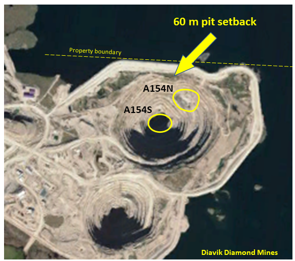
Diavik open pit dikesPit wall setback: Given the size and depth of the open pit, how far must the dike be from the pit crest? Its nice to have 200 metre setback distance, but that may push the dike out into deeper water.
If the dike is too close to the pit, then pit slope failures or stress relaxation may result in fracture opening and increase the risk of seepage flows or catastrophic flooding. The pit wall rock mass quality will be the key determining factor in the setback distance.
Maximizing ore recovery: If the ore zone extends further out into the lake, maximizing ore recovery may require using a steep pit wall along the outer sections of the pit. This may require positioning haulroads with switchbacks along other sides of the pit rather than using a conventional spiral ramp layout.
At Diavik (see image), the A154 north open pit wall was pushed to about 60 metres of the dike to access as much of the A154N kimberlite ore as possible. Haulroads were kept to the south side of the pit.
It may be possible to recover even more ore by pushing out the dike even further. However, this may result in a larger and costlier dike or even require a different style of dike. There will be a tradeoff between how much additional ore is recovered versus the additional cost to achieve that. There will be a happy medium between what makes both technical sense and economic sense.

Design Issues

Once the approximate location of the dike has been identified, the next step is to examine the design of the dike itself. Most of the issues to be considered relate to the geotechnical site conditions.
Lakebed foundation sediments: What does the lakebed consist of with respect to soft sediments? Soft sediments can cause dike settlement and cracking, or mud-waving of fill material.
Will the soft sediments need to be dredged prior to construction, and if so, where do you dispose of this dredge slurry, and what impact will dredging have on the lake turbidity?
Lakebed foundation gravels: Are there any foundation gravel layers that can act as seepage conduits beneath the dike? If so, will these need to be sub-excavated, or grouted, or cut off with some type of barrier wall?  Sonic drilling, rather than core drilling, is a better way to identify the presence of open gravel beds.
Upper bedrock fracturing: Is the upper bedrock highly fractured, thereby creating leakage paths? If so, then rock grouting may be required all along the dike path to seal off these fractures.
Major faults: Are there any major faults or regional structures that could connect the open pit with the lake, acting as a source of large water inflow?. At Diavik, we attempted to characterize such structures with geotechnical drilling before construction. Upon review, I understand there was one such structure not identified, which did result in higher pit inflows until it was eventually grouted off.
Water level fluctuations: In a lake or river one may see seasonal water level fluctuations as well as storm event fluctuations. The height of the dike above the maximum water level (i.e. freeboard) must be considered when sizing the dike.
Ice scouring: In a lake or river that freezes over, ice loads can be an important consideration. During spring breakup as the ice melts, large sheets of ice can be pushed around and may scour or damage the crest of the dike. The dike must be robust enough to withstand these forces.
Construction materials available on site: Is there an abundance of competent rock for dike fill? Is there any low permeability glacial till or clay that can be used in dike construction? If these materials are available on site, the dike design may be able to incorporate them. If such materials are not available, then a alternate dike design may be more appropriate, albeit at a cost.

Conclusion

Each mine site is different, and that is what makes mining into water bodies a unique challenge. However many mine operators have done this successfully using various approaches to tackle the challenge.
Even at the exploration stage, while you are still core drilling the orebody through the ice, you can start to collect some of this information to help figure it all out.
The bottom line is that while mining into a water body is not a preferred situation, it doesn’t mean the project is dead in the water. It will add capital cost and environmental permitting complexity, but there are proven ways to address it.
On the opposite side, I have also seen situations where a dike solution was not feasible, so ultimately there are no guarantees that engineers can successfully address every situation. Lets hope your project isn’t one of them.
There could be a 3rd part to this post that discusses issues associated with underground mining beneath bodies of water; however that is not my area of expertise.  I would be more than happy to collaborate on a article with someone willing to share their knowledge and experience on that subject.
Note: You can sign up for the KJK mailing list to get notified when new blogs are posted. Follow me on Twitter at @KJKLtd for updates and other mining posts. The entire blog post library can be found at https://kuchling.com/library/
Share

Mining Under Lakes – Part 1: Examples

Mining Under Lakes
Springpole Project

Springpole Project

I recently saw an investor presentation from First Mining Gold about their Springpole Project. The situation is that their open pit is located within a lake and will require the construction of a couple of small cofferdams to isolate the pit area from the lake. The concept is shown in this image.
Over the last couple of years I have been involved in a few early-stage studies for mining projects in which nearby bodies of water play a role in the design.    In Canada’s north there are thousands of lakes and rivers, so its not surprising to find mines next to them.
That got me thinking about how many other mines are in the same situation, i.e. projects that may be located very close to, or within, a lake, river, or ocean. Hence I have compiled a short list of a few such mines.
I have been directly involved with some of those in the list, while others are only known to me with limited detail. Some mines I had never heard of before, but their names were provided to me by some Twitter colleagues.
My observation is that building a mine within, or adjacent to, a body of water is nothing new and this has been done multiple times successfully.
Some of these projects may refer to the dams as “dikes”, “cofferdams”, “sea walls” but I assume they are all providing roughly the same function of holding back water for the life of the project.  They are not viewed as permanent dams.
This is Part 1 of a two-part blog post. Part 1 provides some examples of projects where water bodies were involved in the design. Part 2 provides a discussion on specific geotechnical and hydrogeological issues that would normally have to be examined with such projects.

Some Lake Mining Examples

The following are some examples of operating mines involving lakes. I have captured a few Google Earth images, unfortunately some have only low resolution vintage satellite imagery.

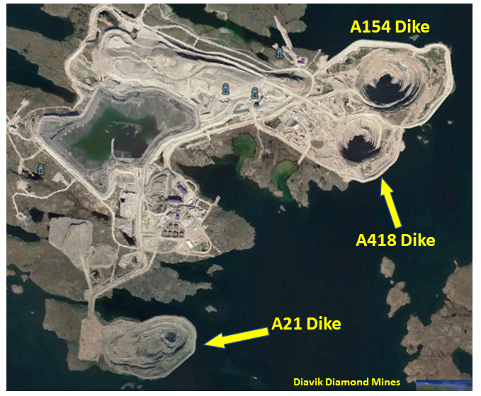
Diavik Diamond Mines, NWT

This is a project I was working on with in 1997 to 2000 while it was still at the design and permitting stage.  My role focused on pit hydrogeology and geotechnical as well as mine planning.
The project would require the construction of three dikes in sequence to mine four lakebed kimberlite pipes.
The three dikes were named after the associated kimberlite pipe being mined inside it; A154, A418, and A21.
The first dikes were built in 2002 and the last dike (A21) was completed in 2018.
The total dike length for the three dikes is about 6.2 km.
For those interested in learning a bit more about Diavik, I have posted an earlier article about the open pit hydrogeology there, linked to at " Hydrogeology At Diavik – Its Complicated".
Diavik mines

Gahcho Kue, NWT

This is a DeBeers diamond project was built in 2016 and required the construction of several small dikes to allow access for open pit mining.    The photos show the pre-mining situation and the site as it is today.   One can see the role the lake would play in the site layout and the need for multiple small dikes.
Gahcho Kue diamond mine

Meadowbank, NWT

This is an Agnico-Eagle gold mining operation built in 2010 that required a cofferdam to be built around one of their open pits (see image).
The total dike length is about 2000 metres.   I don't know much more about it than that unfortunately.
Meadowbank Mine

Cowal Gold Mine, Australia

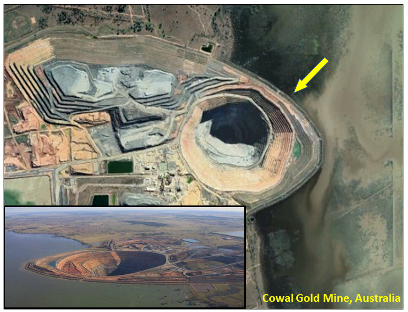
Yes, a lake in Australia ! This is a former Barrick operation, now owned by Evolution Mining, and is another example where the mine is located within the shoreline of a lake (Lake Cowal).    I don't know much about this, the name was kindly provided to me by a colleague.
The total dike length appears to be about 3000 metres.
Cowal Gold Mine

Rabbit Lake Sask

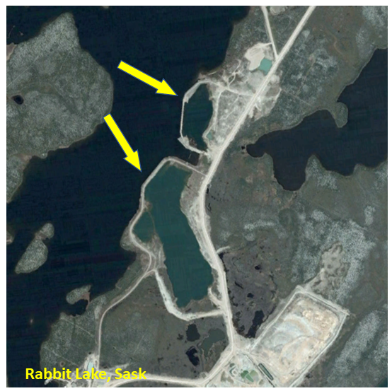
The historical Rabbit Lake uranium mining operation required the construction of cofferdams around a few of their open pits.  They are now reclaimed and flooded.
Rabbit Lake uranium

St Ives Gold Mine, Australia

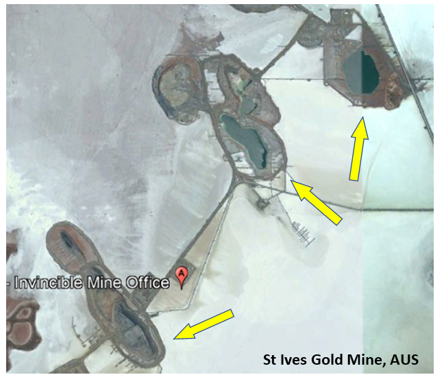
This is a unique situation in that several pits are located within an ephemeral (intermittent) salt lake and dikes were required to prevent pit flooding during wet season.
St Ives gold mine

Some River Mining Examples

The following are some examples of operating mines involving rivers.  Rivers provide a somewhat different design challenge since they have flowing water, who's volume and velocity may change seasonally.    Constrictions in the river created by the dike itself may increase the flow velocity and erosion potential.

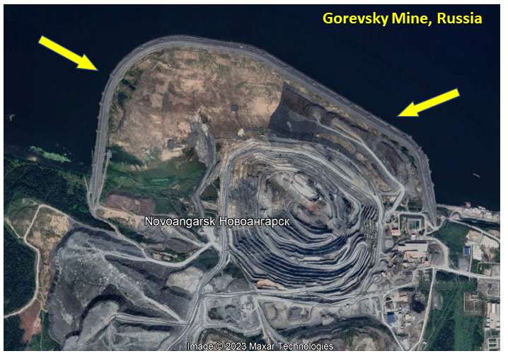
Gorevsky Mine, Siberia

This lead-zinc operation has an orebody that extends into the Angara River.
This mine has built a fairly large cofferdam into the river, and is currently mining a large pit within it.  The total cofferdam length appears to be about 4000 metres.
It would be interesting to see how close the pit will get to the cofferdam.   We'll check back in a few years.
Gorevsky Mine

BHP Suriname Bauxite Mine

This is a project I was involved with several years ago.  The bauxite deposit extends beneath the Suriname River and the goal was to mine as much ore as possible.
Given the flow rates in the river, especially during the wet season, it would be difficult to maintain a cofferdam out into the river.
The shoreline overburden consisted of sands and soft clays, so the decision as made to construct a sheet piling wall along the river bank to protect the pit from river erosion.   This was mined out successfully and eventually reclaimed.
Suriname Bauxite Mine

McArthur River, Australia

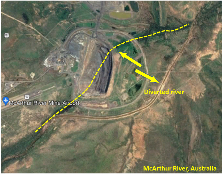
In situations where the river (creek) is small enough and the topography allows, one can divert the entire river around the mine.
There are several examples of this in Canada and elsewhere.  Here’s the McArthur River lead-zinc mine in Australia, where they channeled their small river around the open pit.
McArthur river diversion

An Ocean Example

There are some examples of mining near the ocean. These operations may need to deal with large storm water level surges and large tidal fluctuations.   The Island Copper Mine on northern Vancouver Island is an example where they mined close to the shoreline but not actually into the ocean (as far as I am aware).

Cockatoo Island Mine, Australia

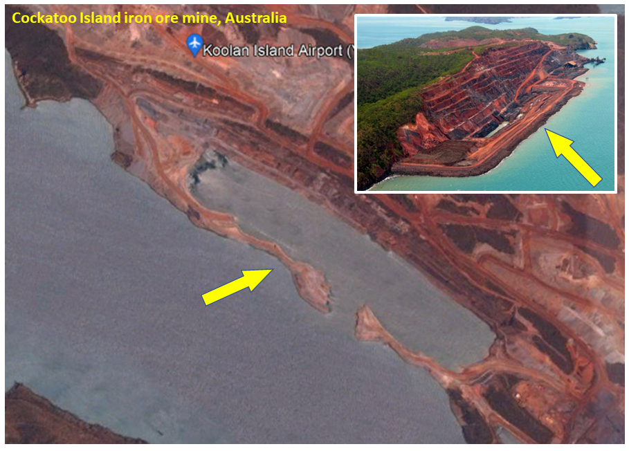
This interesting iron ore mine has an ore zone that dips 60 degrees, is 35 metres wide, with a strike length of more than one kilometre.
A sea wall was constructed to prevent any tidal water from entering the open pit that was to be mined, with reportedly high tidal fluctuations there.
Cockatoo iron mine

Conclusion

As one can see, the idea of mining into a body of water is nothing new.   Its not a preferred situation, but it can be done economically and safely.   The technical challenges are straightforward, and engineers have dealt with them before.  However there also are instances where the design could not economically address the water issue, and thus played a role in the mine not getting built.
If you know of other mines not listed above that have successfully dealt with a water body, please let me know and I can update this blog post.
This concludes Part 1.  Part 2 can be read at this link " Mining Under Lakes – Part 2: Design Issues" discusses some of the concerns that engineers need to consider when building a mine in these situations.

Pantai Remis tin mine

Finally, the worst-case scenario is shown in this grainy video of a tin mine (Pantai Remis Mine) pit slope failure.  It seems they mined too close to the ocean.  Watch to the end, its hard to believe. Its looks like something out of a Hollywood disaster movie.


Note: You can sign up for the KJK mailing list to get notified when new blogs are posted. Follow me on Twitter at @KJKLtd for updates and other mining posts.   The entire blog post library can be found at https://kuchling.com/library/
Share

NPV and Sustainable Mining – Friends or Foes

I recently wrote a blog about the term “sustainable mining” and the different perspectives to it. Does sustainable mining mean having a long term sustainable mining industry or does it mean providing sustainable benefits to local communities? There are two ways you can look at it. If interested, the link to that blog is here.
It’s no surprise that the mining industry wants to promote more sustainable mining practices. It’s the right thing to do. However, in my experience, sometimes NPV analysis can be at conflict with sustainable mining practices. That opinion is from my engineering perspective.  Those working in the CSR field may have a different view on it.

Majors, mid-tiers, juniors see things differently

There are essentially three different types of mining companies; majors; mid-tiers, and junior miners. They have different financial constraints imposed upon them and these constraints will impact on their decision making.
In general to get financing and investor interest, development projects must demonstrate a high NPV, high IRR, and short payback period. This requirement tends to apply more to the small and mid tiered companies than to the major companies.  The majors normally have different access to financing.
A characteristic of NPV analysis and cashflow discounting is the penalizing of higher upfront costs whilst reducing the economic impacts of longer term deferred costs. This feature, combined with the need to manage NPV, will influence design decisions and operating philosophies.  Ultimately this will impact on the rate of adopting of sustainable mining practices.
Mining companies often have two masters they must try to satisfy. One master is the project investor(s) that wants their investment returns quickly and with limited risk. The second master is the local stakeholder that wants a safe project with long lasting benefits to the community.  NPV analysis often requires trading-off the needs of one master over that of the other. This trade-off is neither right nor wrong; it is simply a reality.
Major miners now seem to have a third master; i.e large pension funds. These funds are now demanding for more sustainable mining practices (mainly tailings related) and mining companies are trying to comply. Smaller mining companies thus far don’t have this third master to satisfy, although that may come soon. Hence smaller miners are apt to follow a somewhat different path with regards to sustainable mining implementation. NPV plays a significant role in their decision making.

NPV…friend or foe

executive meetingThere are several scenarios where NPV analysis decision making may conflict with the objectives of sustainable mining. Here are a few examples.
1. Minimizing capital expenditures at the expense of operating costs. The likelihood of success in creating a long life sustainable mine will improve by having low metal cash costs. Naturally there will be a benefit in having low operating costs. However sometimes achieving low operating costs will require higher capital investments. For example, this could involve using large capacity material handling mining systems (IPCC) to lower unit costs.
NPV analysis will tend penalize these large investments by discounting the future operating cost savings. Being in the lowest cost quartile is good thing; being in the highest cost quartile isn’t.  Higher operating costs can hurt the long term sustainability of an operation, especially during downturns in commodity prices.
2. Tailings disposal method trade-offs are affected by NPV analysis. Currently there is an industry push towards safer and sustainable tailings storage methods, like paste or dry stack. However the upfront processing and materials handling capex can be significant. Hence less desirable conventional style tailings disposal may often be the winners in tailings trade-off studies due to NPV.
3. Closure considerations incorporated in the early mine design stage are affected by NPV analysis. A large cost component of mine closure is related to waste rock and tailings reclamation. However since final closure costs are  deferred, they might be given less consideration in the initial design. In many studies, high closure costs can be deemed insignificant in the project NPV due to discounting. Eventually these high costs will need to be incurred.  Unfortunately they might have been mitigated by wise decision making earlier in the project life.
4. Low grade ore stockpiling can help to increase early revenue and profit, thereby improving the project NPV and payback. Stockpiling of low grade and prioritization of high grade means that lower grade ore will be processed in the later stages of the project life.  Who hasn’t been happy to develop a mine schedule with the grade profile shown on the right?
If low grade years are coupled with a dip in metal price cycles, the mine could become economically unsustainable.  Shutting down a mine and putting it on “care and maintenance” is short term in intention but often long term in duration (over 30 years in some cases).
Mark Bristow of Barrick briefly discussed the issue of high grading in this interview.
5. Low strip ratios in the early stages of a project are often a feature of the ore body itself. However mine plans can also be designed to defer high strip ratios into the future via the use of proper pit phasing. This is another way to defer operating costs into the future. The NPV will see the benefit, long term sustainability may not.
6. Project life selection based on NPV analysis may not show significant economic difference between a 15 year project and one with a life of 25 years. Project decisions could then favor a short life project. This could relate to smaller pit pushbacks, smaller tailings ponds, smaller waste dumps, and easier permitting.  Possibly the local community would prefer a long life project that provides more sustainable jobs and business opportunities. NPV may see it differently.
7. Accelerated depreciation, tax and royalty holidays are types of economic factors that will improve NPV and early payback. They are one tool governments use to promote economic activity. These tax holidays will greatly enhance the NPV when combined with high grading and waste stripping deferral.
Unfortunately reality hits once the tax holiday is over and suddenly taxes or royalties become payable. At the same time head grades may be decreasing and strip ratios increasing. Future cashflows may carry an additional economic burden, which may conflict with the goal of a sustainable mine.

Conclusion

NPV is one of the standard metrics used to make project decisions. The deferral of upfront costs in lieu of future costs is favorable for cashflow and investor returns. Similarly, increasing early revenue at the expense of future revenue does the same.   Both approaches will help satisfy the financing concerns. However they may not be advantageous for creating long term sustainable projects.
Riskier projects will warrant higher discount rates.  This can magnify the importance of early cashflows even more and future cashflows become even less important.
It will be interesting to see how we (the mining industry) respond as industry leaders make greater commitments to sustainable mining. Both majors and juniors will equally need to work on keeping those commitments.  Will NPV analysis help or hurt?


Note: You can sign up for the KJK mailing list to get notified when new blogs are posted.  Follow us on Twitter at @KJKLtd for updates and insights.
Share

Sustainable Mining – What Is It Really?

We hear a lot about the need for the mining industry to adopt sustainable mining practices. Is everyone certain what that actually means? Ask a group of people for their opinions on this and you’ll probably get a range of answers.   It appears to me that there are two general perspectives on the issue.
Perspective 1 tends to be more general in nature. It’s about how the mining industry as a whole must become sustainable to remain viable. In other words, can the mining industry continue to meet the current commodity demands and the needs of future generations?
Perspective 2 tends to be a bit more stakeholder focused. It relates to whether a mining project will provide long-term sustainable benefits to local stakeholders. Will the mining project be here and gone leaving little behind, or will it make a real (positive) difference? In other words, “what’s in it for us”?
There are still some other perspectives on what is sustainable mining. For example there are some suggestions that sustainable mining should have a wider scope. It should consider the entire life cycle of a commodity, including manufacturing and recycling. That’s a very broad vision for the industry to try to satisfy.

How might mining be sustainable?

The solutions proposed to foster sustainable mining depend on which perspective is considered.
With respect to the first perspective, the solutions are board brush. They generally revolve around using best practices in socially and environmentally sound ways. A sustainable mining framework is typically focused on reducing the environmental impacts of mining.
Strategies include measuring, monitoring, and continually improving environmental metrics. These metrics can include  minimizing land disturbance, pollution reduction, automation, electrification, renewable energy usage, as well as proper closure and reclamation of mined lands.
Unfortunately if the public hates the concept of mining, the drive towards sustainability will struggle. Trying to fight this, the industry is currently promoting itself by highlighting the ongoing need for its products. Unfortunately some have interpreted this to mean “We make a mess because everyone wants the output from that mess”. I’m not sure how effective and convincing that approach will be in the long run.

Focusing on localized benefits

If one views sustainable mining from the second perspective, i.e. “What’s in it for us”, then one will propose different solutions. Maximizing benefits for the local community requires specific and direct actions. Generalizations won’t work.  Stakeholder communities likely don’t care about the sustainability of the mining industry as a whole.
They want to know what this project can do for them. Will the local community thrive with development or will they be harmed? Are the economic benefits be short lived or generational in duration? Can the project lead to socio-economic growth opportunities that extend beyond the project lifetime? Will the economic benefits be realized locally or will the benefits be distributed regionally?
One suggestion made to me is that all mining operations be required to have long operating lives. This will develop more regional infrastructure and create longer business relationships. A mine life of ten years or less may be insufficient to teach local entrepreneurship.  It maybe too short to ensure the long term continuation of economic impacts. Mine life requirement is an interesting thought but likely difficult to enforce.
Nevertheless the industry needs to convince local communities about the benefits they will see from a well executed mining project. Ideally the fear of a mining project would be replaced by a desire for a mining project. Preferably your stakeholders should become your biggest promoters. Working to make individual mining projects less scary may eventually help sustain the entire industry.

What can the industry do?

We have all heard about the actions the industry is considering when working with local communities. Some of these actions might include:
  • Being transparent and cooperative through the entire development process.
  • Using best practices and not necessarily doing things the “cheapest” way.
  • Focusing on long life projects.
  • Helping communities with more local infrastructure improvements.
  • Promoting business entrepreneurship that will extend beyond the mine life.
  • Transferring of post-closure assets to local communities.
There are teams of smart people representing mining companies  working with the local communities. These sustainability teams will ultimately be the key players in making or breaking the sustainability of mining industry.  They will build and maintain the perception of the industry.
While geologists or engineers can develop new technology and operating practices, it will be the sustainability teams that will need to sell the concepts and build the community bridges.
The sustainability effort extends well beyond just developing new technical solutions. It also involves politics, socio-economics, personal relationships, global influences, hidden agendas. It can be a minefield to navigate.

Conclusion

As a first step, the mining industry needs to focus more on local stakeholders and communities. Remove the fear of a mining project and replace it with a desire for a mining project. Mining companies must avoid doing things in the least expensive ways. They must do things in ways that inspire confidence in the company and in the project.
The ultimate goal of sustainable mining will require changing the public’s attitude about mining. Perhaps this starts with the local grass roots communities rather than with global initiatives. As a speaker said at the recent Progressive Mine Forum in Toronto, the mining industry has lost trust with everyone. It is now up to the mining companies, ALL OF THEM, to re-establish it. Unfortunately just one bad apple can undo the positive work done by others.  The industry is not a monolith, so all you can do is at least make sure your own company inspires confidence in the way you are doing things.
As an aside, I have recently seen suggestions that discounted cashflow analysis (i.e. NPV analysis) and sustainable mining practices may be contradictory. There may be some truth to those comments, but I will leave that discussion for a future blog.  You can read that blog at this link.
Note: You can sign up for the KJK mailing list to get notified when new blogs are posted.
Share

Green Energy Storage Using Abandoned Mines

The mining industry is always looking for ways to rehabilitate their abandoned operations so that there may be a public use for them. This could entail leaving behind recreational lakes, building golf courses, creating nature parks or using empty pits as public landfills. Another rehabilitation idea being studied is using old underground mines as a means of green energy storage.  If successful, we do have a lot of abandoned mines in all regions of the country.

Compressed air can store energy

I was at the 2019 Progressive Mine Forum in Toronto and a presentation was given on underground compressed air storage. The company was Hydrostor (https://www.hydrostor.ca/).  They were promoting their Advanced Compressed Air Energy Storage (A-CAES) system.
It is a technology that addresses the power grid need for power transmission deferral services. The A-CAES system can theoretically provide low-cost, long duration bulk energy storage (i.e. hundreds of MWs, 4-24+ hour duration).
The idea is to store off-peak or excess power from solar, wind, or other generating source.  Then the system can release this power back into the system during peaks or low generation capacity. Solar and wind power normally don’t work as well at night.


Flood the mine

The system uses excess electricity to run a compressor, producing heated compressed air. Initially heat is extracted from the air and retained inside a thermal store.  This preserves the heat energy for later use. Next the compressed air is stored in the underground mine, keeping a constant pressure.
While charging, the compressed air displaces water out of the mine, up a water column to a surface reservoir.
On discharge, water flows back down forcing air to the surface where it is re-heated using the stored heat and expanded to generate electricity.
Imagine an underground mine beneath an open pit, and seeing the open pit water level rise and fall daily as the compressed air is recharged underground and then released.
Hydrostor is currently building a $33 million 5-MW project in Australia at the Angas Zinc Mine site. I asked Hydrostor if they had any white papers describing the economics for a typical abandoned mine we might see here in Canada. Unfortunately they don’t have such a case study available.
Update: A Canadian example recnetly came to light; “How an old Goderich salt mine could one day save you money on your hydro bill“.
No doubt there would be capex and opex costs to build and operate the plant, but these would hopefully be offset by the power generation. It just not clear over what time horizon this payback would occur. Many abandoned underground mines are already in place; they are just waiting to be exploited.

Permitting is still an issue

Converting an abandoned mine into a power storage facility will still have its challenges. Cost and economic uncertainty are part of that.  In addition, permitting such a facility will still require some environmental study.
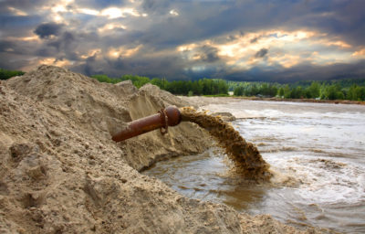
At Hydrostor’s proposed Australian operation, a fairly extensive environmental impacts assessment still had to be completed (see the link here).
Noise, vibration, air quality, ecology, traffic, surface water, groundwater impacts, visual impacts, employment, and indigenous consultations are aspects that would need to be addressed. However, given that this would be a green energy application, one might be able to get all stakeholders on board quickly.

Conclusion

We hear about sustainable mining and the desire to extend the positive social and economic impacts of a mining project. Energy storage is one way to extend the mine life into perpetuity by creating a localized power grid. Simply use wind or solar to recharge the system and then generate power over night.
If anyone is aware of a situation where something similar has been done, let me know and I will share it. Perhaps one day Hydrostor will provide a detailed economic study for a typical Canadian mine so that mining companies can see the economic potential.
Update:  In 2021 Hydrostor announced that it is developing two 500MW/5GWh energy storage projects in California, each of which would be the world’s largest non-hydro energy storage system ever built.  Read more at this link “Gigawatt-scale compressed air
Note: You can sign up for the KJK mailing list to get notified when new blogs are posted.For those interested in reading other mining blogs, check out the Feedspot website at the link below. They have over 50 blog sites you check out. https://blog.feedspot.com/mining_blogs/
Share

Mineral Processing – Can We Keep It Dry?

It’s common to see mining conferences present their moderated panels discussing “disruption” and Mining 2.0.   The mining industry is always looking for new technologies to improve the way it operates. Disruptive technologies however require making big changes, not tweaks.  True disruption is more than just automating haulage equipment or having new ways to visualize ore bodies in 3D.
Insitu leaching is a game changing technology that will eventually make a big difference.  Read a previous blog at “Is Insitu Leaching the “Green Mining” Future”.  Development of this technology will negate the need to physically mine, process, and dispose of rock.  Now that’s disruptive.
However, if we must continue to mine and process rock, then what else might be a disruptive technology ?

Is dry processing a green technique

Process water supply, water storage and treatment, and safe disposal of fine solids (i.e. tailings) are major concerns at most mining projects.
Recently I read an article titled “Water in Mining: Every Drop Counts”.
That discussion revolved around water use efficiency, minimizing water losses, and closed loop processing.   However another area for consideration is whether a future technology solution might be dry processing.

Dry processing is already being used

By dry processing, I am not referring to pre-concentration ore sorting or concentrate cleanup (X-ray sorting). I’m referring to metal recovery at the mineral liberation particle size.
In Brazil Vale has stated that it will spend large sums of money over the next few years to further study dry iron ore processing. By not using water in the process, no tailings are generated and there is no need for tailings dams.
Currently about 60% of Vale’s production is dry (this was a surprise to me) and their goal is to reach 70% in the next five years.   It would be nice to eventually get to 100% dry processing at all iron ore operations.   The link to the article is here “Vale exploring dry stacking/magnetic separation to eradicate tailings dams”.

Is dry grinding possible

Wet grinding is currently the most common method for particle size reduction and mineral liberation.  However research is being done on the future application of dry grinding.
The current studies indicate that dry grinding consumes higher energy and produces wider particle size distributions than with wet grinding. However it can also significantly decrease the rate of media consumption and liner wear.
Surface roughness, particle agglomeration, and surface oxidation are higher in dry grinding than wet grinding, which can affect flotation performance.
Better understanding and further research is required on the dry grind-float process. However any breakthroughs in this technology could advance the low water consumption agenda.
You can learn more about dry grinding at this link “A comparative study on the effects of dry and wet grinding on mineral flotation separation–a review”.

Electrostatic separation

Electrostatic separation is a dry processing technique in which a mixture of minerals may be separated according to their electrical conductivity. The potash industry has studied this technology for decades.
Potash minerals, which are not naturally conductive, are conditioned to induce the minerals to carry electrostatic charges of different magnitude and different polarity.
In Germany, researchers have developed a process for dry beneficiation of complex potash ores. Particle size, conditioning agents and relative humidity are used to separate ore.
This process consumes less energy than conventional wet separation, avoiding the need to dry out the beneficiated potash and the associated tailings disposal issue.
Further research is on-going.


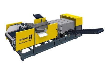
Eddy current separators

The recovery of non-ferrous metals is the economic basis of every metal recycling system. There is worldwide use of eddy separators.
The non-ferrous metal separators are used when processing shredded scrap, demolition waste, municipal solid waste, packaging waste, ashes from waste incineration, aluminium salt slags, e-waste, and wood chips.
The non-ferrous metal separator facilitates the recovery of non-ferrous metals such as aluminium, copper, zinc or brass.
This technology might warrant further research in conjunction with dry grinding research to see if an entirely dry process plant is possible for base metals or precious metals.  Learn more at the Steinert website.

Conclusion

Given the contentious nature of water supply and slurried solids at many mining operations, industry research into dry processing might be money well spent.
Real disruptive technologies require making large step changes in the industry. In my opinion, insitu leaching and dry processing are two technologies that we will see more of over the next 20 years.
Ultimately the industry may be forced to move towards them due to environmental constraints.  Therefore let’s get ahead of the curve and continue researching them.


Note: You can sign up for the KJK mailing list to get notified when new blogs are posted.
For those interested in reading other mining blogs, check out the Feedspot website at the link below.  They have over 50 blog sites you check out.  https://blog.feedspot.com/mining_blogs/
Share

Power Generation & Desalinization – An Idea that Floats

Access to a fresh water supply and a power supply are issues that must be addressed by many mining projects. Mining operations may be in competition with local water users for the available clean water resources. In addition, the greenhouse gas emissions from mine site power plants are also an industry concern. If your project has both water and power supply issues and it is close to tidewater, then there might be a new solution available.
I recently attended a presentation for an oil & gas related technology that is now being introduced to the mining industry. It is an innovative approach that addresses both water and power issues at the same time.
The technology consists of a floating LNG (liquefied natural gas) turbine power plant combined with high capacity seawater desalinization capabilities. MODEC is offering the FSRWP® (Floating Storage Regasification Water-Desalination & Power-Generation) system.
MODEC also has associated systems for power only (FSR-Power®) and water only (FSR-Water®)

FSRWP capabilities

The technology is geared towards large capacity operations that have access to tidewater. It provides many tangible and intangible operational and environmental benefits.  It can:
  • Generate fresh water supply (10,000 – 600,000 m3 /day)
  • Generate electrical power (80 to 1000 MW) using LNG
  • Can provide power inland (>100 km) from a tidewater based floating power plant
  • Can provide natural gas distribution on land via on-board re-gasification systems
  • Has LNG storage capacity of 135,000 cu.m
  • Has a refueling autonomy of 20 to 150 days
  • Allows low cost marine delivery of bulk LNG supply

Procurement & Application

The equipment can be procured in several ways. For instance it can be contracted as an IPP (Independent Power Producer), purchased as an EPCI (Engineering, Procurement, Construction and Installation), BOO (Build, Own and Operate) or BOOT (Build, Own, Operate and Transfer).
Typically it takes 18-24 months of contract award to deliver to the project site, although temporary power solutions can be provided within 60-90 days.
From a green mining perspective, the FSRWP produces clean power with the highest thermal efficiency and lowest carbon foot-print.
See the table for a comparison of different power generation efficiencies and carbon emissions per kW.
Gas turbines are not new technology to MODEC.  They currently own & operate 42 such generators, which can produce roughly 43 MW (each) in combined-cycle mode.

Mooring options

Currently there are three mooring options for the floating system that should fit most any tidewater situation.
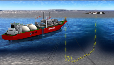
Jetty or Dolphin mooring is suitable for protected areas or near-shore applications where the water depth is in the range of 7 to 20 meters.
Tower Yoke mooring is ideal for relatively calm waters where the water depth is between 20 to 50 meters.
External Turret mooring is similar to a Tower-Yoke and is ideal for water depths exceeding 50 meters or where the seabed drops off steeply into the ocean.

Power transmission

Twenty years ago it was impractical to transmit AC power long-distances and subsea power cable technology was not as advanced as it is today. Hence an offshore power plant like a FSRWP was not technically viable. Due to R&D efforts over the last 15 years it is now possible to economically transmit AC. For example it is possible to transmit up to 100 MW over 100 miles through a single subsea cable. In addition, it is also viable to transit 200 MW at 145 kV from a vessel to shore.

Water treatment

Modern FSRWP’s use reverse osmosis membrane technology to produce industrial or potable water.  This is similar to most conventional onshore desalination plants.
The main benefits of floating offshore desalination are increased overall thermal efficiency if both power and water production are combined on a single vessel. In addition, seawater sourced offshore and rejected brine discharged offshore minimizes risk to coastal marine life.

Conclusion

The bottom line is that if your mining project is near shore, and has both water supply and power issues, take a look at the FSRWP technology. One might say it is greener technology by using LNG (rather than coal, heavy fuel oil, or diesel) to generate power.  At the same time it avoids competition with locals for access to fresh water.
This technology won’t be suitable for all mining situations, but perhaps your mine site fits the model. Reportedly rough costs for power are in the range of $0.10-$0.14/kwh with a capital cost of $1M-$1.5M per MW.
There will be minimal closure costs associated with dismantling the power plant.  One just floats it away at the end of the mine life.
Check out the MODEC website if you wish to learn more: https://www.modec.com/fps/fsrwp/index.html
Note: If you would like to get notified when new blogs are posted, then sign up on the KJK mailing list on the website.  Otherwise I post notices on LinkedIn, so follow me at: https://www.linkedin.com/in/kenkuchling/.
For those interested in reading other mining blogs, check out the Feedspot website at the link below. They list 60 mining related blog sites that you check out. https://blog.feedspot.com/mining_blogs/
Share

Global Risks – Our Fears Are Evolving

Recently I wrote a blog about how the adoption of new technology in the mining industry will increase the risk of cyber crime. However this is just one of many risks the industry faces today.  This raises the question as to what are the main risks impacting all global businesses.  Luckily for us, the World Economic Forum undertakes an annual survey on exactly this subject.
Each year business leaders are queried about what they view as their major risks. The survey results are summarized in the Global Risk Report.
The 2019 report can be downloaded at this link. http://www3.weforum.org/docs/WEF_Global_Risks_Report_2019.pdf.
The study rates risks according to the categories “likelihood” and “impact”. A risk could have a high likelihood of occurring but have a low economic impact. One might not lose sleep over these ones.
Another interesting feature in the report is seeing how the top risks change from year to year.  Some risks from 10 years ago are no longer viewed as key risks today.

2019 risk situation

In 2019 environmental related risks dominate the survey results. They account for 4 of the top 5 risks by “impact” and 3 of the top 5 by “likelihood”. Technology related concerns about data fraud and cyber-attacks were also viewed as highly likely (#4 and #5). See the image below for the top 5 risks in each category.
Although the Global Risk survey wasn’t specifically directed at the mining industry, all of the identified risks do pertain to mining.


10 year risk trend

It is also interesting to look at the detailed 10 year  table in the report to see how the risk perceptions have changed over the last decade.
None of the top five “Impact” risks from ten years ago are still in the top five now and only two from 2014 still exist. In the “likelihood” category, a similar situation exists.
It will be interesting to compare the 2024 list with 2019 list to see how risks will continue to evolve.

How about the mining industry

EY Global Mining & Metals also undertake a risk survey, focused on mining only. You can read their article at this link “The Top Risks Facing Mining and Metals”.  Their top 10 risks are listed below, many are different than those from the World Economic Forum ranks. You must read the EY article to fully understand the details around their risk items.
  1. License to operate (difficulty to acquire)
  2. Digital effectiveness (lack thereof)
  3. Maximizing portfolio returns (can this be done)
  4. Cyber security (increasing risk of attack)
  5. Rising costs (can costs be controlled)
  6. Energy mix (acceptable power sources)
  7. Future of workforce (lack of interest in the sector)
  8. Disruption (falling behind competitors)
  9. Fraud (increasing sophistication)
  10. New world commodities (versus reduced demand for some commodities)

Conclusion

My bottom line is that the Global Risk Report is something that we should all read. Download it and then compare with what your company sees as its greatest risks. The only way to mitigate your risks is to know what they are.  The only way to work with others is to know what their issues are.
Note: If you would like to get notified when new blogs are posted, then sign up on the KJK mailing list on the website.  Otherwise I post notices on LinkedIn, so follow me at: https://www.linkedin.com/in/kenkuchling/.
Share