Every now and then I discover a new technology or platform that I feel can play a key role in the mining industry going forward. I also come across others that, in my opinion, will struggle to gain traction, knowing the industry as I do.
One intriguing platform that has caught my recent attention is related to mine waste risk management. This platform has been in development for a few years but recently reached the commercial launch milestone. The name of it is the Critical Infrastructure Risk Decision Basis (CI-RiskDB).
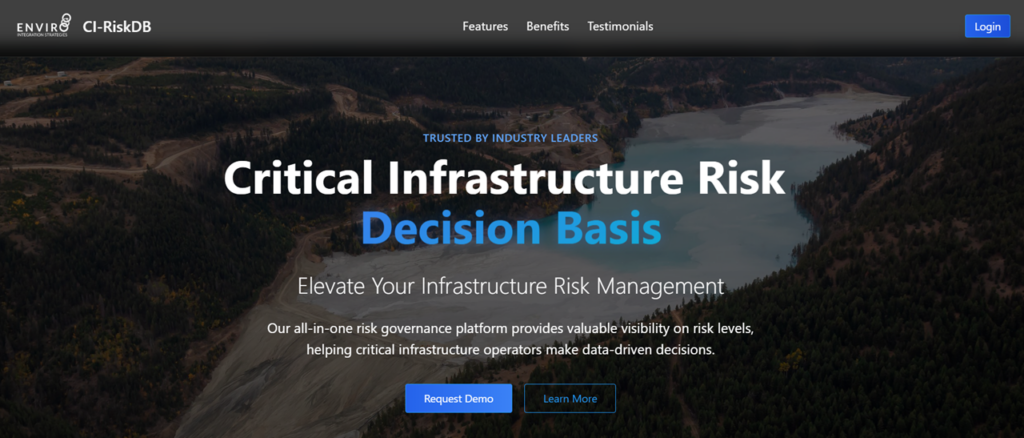
It is being developed by a Saskatoon based team at Enviro Integration Strategies and is intending to help manage risks associated with tailings, water, waste rock and heap leach facilities at mining operations. A heap leach pile is not exactly waste, until the leaching process is complete, but these facilities operate under the same types of risk as the other facility types included.
The CI-RiskDB platform has been designed on the risk assessment framework used by Agnico Eagle Mines, and aligned with current global best practices and standards. Agnico has been a co-developer of the back-end processes, and collaborator and reviewer of the platform design all the way along. It certainly helps to have some mine operator input when developing anything new for the mining industry.
Mining industry standardization is something I have always been a big proponent of. My years of undertaking numerous mining due diligences has shown me that the industry has a knack for each company doing things their own way. However, some industry-wide standardization of risk processes might be warranted given the extremely critical nature of tailings dams and other mine site embankments.
Regarding the CI-RiskDB online platform, I was given free demo access. I was able to poke around, examine methodologies, capabilities, and hence get a feel for how the application works. After my brief period of using it, I am in no way an expert on it. However, I can see that likely in less than 8 hours of use (or training) one should become very comfortable with the system functionality.
Benefits of the Platform
 In my view, having a single industry platform for critical infrastructure risk management provides several benefits. These are:
• The CI-RiskDB platform provides consistency in the approach used to define and assess risk, which is important given the industry’s issue with employee turnover and lack of experienced technical personnel. A consistent platform will make it easier to accommodate personnel movement within companies and within supporting consultancies.
• The platform provides a complete risk story per site facility (i.e. tailings dam) by quantifying risk relative to other site facilities, and documenting actions to lower risks. This system is designed specifically for geo-infrastructure that rely on geotechnical stability analyses. It requires the users to identify all the ways that hazards, uncertainties, gaps in knowledge and poor quality of work can introduce risks to the facility.
• The CI-RiskDB platform provides a basis for both a risk assessment (risk ranking) and a Level of Practice (LOP) or maturity assessment. The LOP was something I personally had never heard of before. The LOP assessment represents a way to identify, quantify, and mitigate the numerous uncertainties one has in the design and operation of a mining facility.
• The platform can provide a repository for all documents pertaining to the facilities, linked directly to actions and risks they are related to, and other system knowledge such as actions status and progress, history of changes over time, and who made the changes and updates. It is then possible to find all relevant information in one place, including design reports, review board notes, construction records, performance and monitoring reports. This can be a time savings for all involved, and can support audits, training, onboarding.
• There will be a paper trail for the risk evaluation process, by documenting who provided input, rationale for the input, who did the review and final signoff on the risk scores.
Site Information Structure
The CI-RiskDB platform assesses risk management down to the level of the cross-sectional stability analysis. It subdivides a site down into various operational levels.
SITE ==> FACILITY ==> INFRASTRUCTURE ==> CROSS-SECTION
 Each mine site is unique with its own set of “Facilities”. For example, the individual Facilities could include Tailing Management Area #1, TMA #2, the Heap Leach Pad, Waste Dump #1, Waste Dump #2, etc.
Each Facility can then be further subdivided into separate “Infrastructure”. For each Facility these could include (for example) a North Dam, a South Dam, an East Dam, etc.
Each Infrastructure item can be further classified into separate stability Cross-Sections. For example, the North Dam may have a section 10 metres high and another section at 50 metres high. Perhaps some stability analysis is done at peak shear strength and others using residual shear strength. The stability analysis for each cross-section will be different with unique factors of safety, unique Level of Practice (LOP), and therefore resulting in a unique probability of failure.
Risk Quantification Criteria
The CI-RiskDB platform follows a typical, but adaptable, risk evaluation approach of:
Risk Score = (Probability of Failure) X (Consequence of Failure)
The Probability of Failure is derived from Factor of Safety calculations modified by a Level of Practice score. The Level of Practice (LOP) is a measure of the integrity and quality of data used to design and manage a mine facility. A dam with a Factor of Safety of 1.2 will have a different Annual Failure Probability depending if the design & operation are highly credible (a high LOP) versus a design & operation based on limited field data and technical rigor (low LOP).
For example, by improving operating management or monitoring systems, one may reduce the Probability of Failure without changing anything in the design of the dam itself.
The Consequence of Failure score is derived from scoring on the four factors listed below. Each is scored on a scale of 1 to 5. The overall Consequence Score for the risk evaluation is based on the maximum score of the four factors
-
Health and Safety
-
Material damage
-
Environment
-
Community
Note that the risk categories, definitions, and score settings are adaptable based on a company’s existing risk matrices. This way a company does not need to implement an entirely new system, other than using the CI-RiskDB platform to help manage their information and risk assessment workflow.
Level Of Practice (LOP) Evaluation
 The Level of Practice (LOP) is a measure of the integrity and quality of data used to design and manage a mine facility. The CI-RiskDB platform currently uses 45 criteria to evaluate the LOP associated with a facility. For example, these quality criteria include items such as: current understanding of soil profile; testing & verification between lab and field investigations; stability analysis detail; construction QA/QC undertaken, monitoring programs, etc.
The 45 criteria used for the LOP are categorized into six main categories. They are:
-
Design – Investigation (9 criteria)
-
Design – Testing (6 criteria)
-
Design – Analysis & Documentation (8 criteria)
-
Construction (8 criteria)
-
Operation & Monitoring (10 criteria)
-
Performance (4 criteria)
While not all 45 criteria apply to every facility or Infrastructure, the fact that 45 criteria are defined helps ensure a consistent LOP evaluation process.
Each facility receives an overall LOP score based on 1 to 4 rating for each criteria. As well, the basis for each criteria score is documented, reviewed, and signed off by relevant persons. This provides a documented process that endures despite changes in technical or management personnel.
The LOP score is at a snapshot in time and will evolve as measures are implemented to address areas that were lacking in technical rigor.
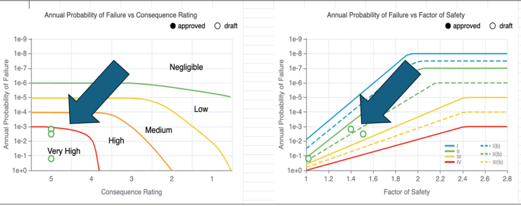
Example Output
The following are some example outputs from the CI-RiskDB platform.

Path to Successful Implementation
Tailings ponds and waste rock dumps are mine facilities that can impact the public far beyond the boundaries of the mine property limit. These facilities need to be taken seriously. Adoption of a platform like CI-RiskDB would move towards enhancing mining industry consistency in risk management.
The selection of individual scores will still be of a subjective nature when deciding what practices are good or poor quality, or whether sufficient rigor was applied to controlling risks. There is also the possibility of people assigning low consequence ratings where high consequence impacts might be possible.
 Over confidence of personnel is something that can unfortunately play a role in risk management. However, the more eyes involved with reviews and signoffs, as well as occasional third party audits, the less likely that this occurs (hopefully).
If a company wishes to successfully implement the CI-RiskDB platform, it will need to make certain time commitments.
1. The company should treat the platform like a collective “diary” about their facilities, ensuring a full onboarding of all past information and reports and a thorough set of evaluations to start.
2. They will need to infill any risk-based information already known, and to have team members add insights about their own knowledge and observations over time. At the least, those involved with the facility must gradually add their knowledge that would otherwise remain “in their heads” or on their personal computers.
3. Companies must then continue to use the platform to record observations, upload performance reports and inspections, other relevant reports, and to update progress on actions and changes in conditions or issues tied to risks. The idea is to move the team away from relying on personal folders and emails, giving everyone involved access to information.
4. Companies must use the built-in governance protocols by running reports to understand what updates and changes have been made over time. Compare the number of actions added versus closed out over a specified period. Is progress being made? Compare the status of performance and risk progression over time and use this to demonstrate action for external audiences.
The CI-RiskDB platform will not maximize its value if a company is unable to make these types of commitments.
Conclusion
 In closing, as of this month December 2025, I understand the Critical Infrastructure Risk Decision Basis platform is currently being piloted and implemented at a number of mine sites in Canada, including Agnico Eagle at a corporate level. Additional pilots may be forthcoming in 2026.
Hence one can expect that with time the platform will incorporate even more industry feedback in its functionality.
If you are interested in taking a deeper dive on the CI-RiskDB, contact the Enviro Integration Strategies’ team at https://ci-riskdb.com.
I would like to thank Karen Chovan for allowing me access to the platform. Since I am not a risk management expert, the time spent poking around was also a good learning experience for me.
Date: Dec 20, 2025

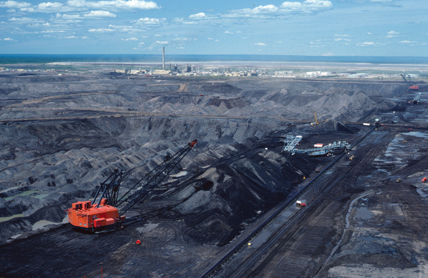
 Syncrude had four large walking draglines, each with a 80 cubic metre bucket and 110 metre operating radius. These were very big machines; you could sit one in the end zone of a football field and the bucket would be digging (or dumping) in the other end zone. Two draglines were on the East side of the mine and two were on the West, mining the oilsand in 25 m wide strips.
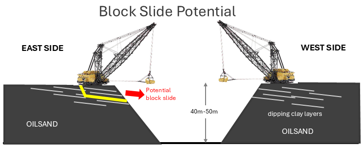 There were numerous instances of East mine block slides, where large portions of the upper slope would fail as large blocks, 50 metres long and up to 30 metres back from the crest. The fear was that if a dragline happened to be sitting on one of these failing blocks, the entire machine would slide along into the pit. Many block slides did occur over the years, but only a few came close to jeopardizing a machine. The geotechnical monitoring programs in place were successful (described later).
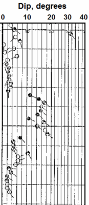 The insitu clay structures were identified using oil and gas borehole logging technology, with tadpole dipmeter plots (see image) used to analyse the bedding (the tail on the tadpole shows the dip direction). The vertical axis is depth from surface or elevation. The geotech engineers would use this information, combined with structural mapping of previously mined faces, to forecast potentially unstable areas.
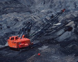
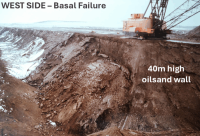 The main geotechnical issue on the West side were basal slope failures, termed this due to sliding along weak clays and muds at the base of the highwall. This photo shows a typical basal failure. Basal failures also occured on the East side.
 Once our engineer-in-training rotation program was complete, we were to be assigned to a more permanent position. For me, that was going to be as an East side geotechnical engineer – ugh!. It’s at that time I decided to look for greener pastures. Three years was long enough from 1980 to 1983; given the amount of learning and responsibility I had undertaken. Other colleagues left the same time, while many other friends stayed in Ft McMurray for their entire careers.
 In Part 1 of this two part blog post I would like to share some stories from the early days of my career working in Fort McMurray.
 At the time Syncrude had an excellent engineer-in-training program for new graduates. Every six months they would rotate engineers into different technical areas.
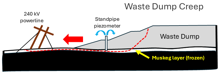 Next we sampled that depth carefully, revealing that frozen muskeg layers were present. When we installed standpipe piezometers in these holes, we saw water flowing out of the top of the pipes. This means the foundation pore pressure is high, way too high.
 For example, one project I had was to monitor the performance of different brands and styles of conveyor idlers. We would track about 2,000 individual idlers; when they were installed on the conveyors; when they were removed, why they were removed (bearing failure, cover failure, something else).
 The mining industry is implementing more and more technology in the mining cycle.
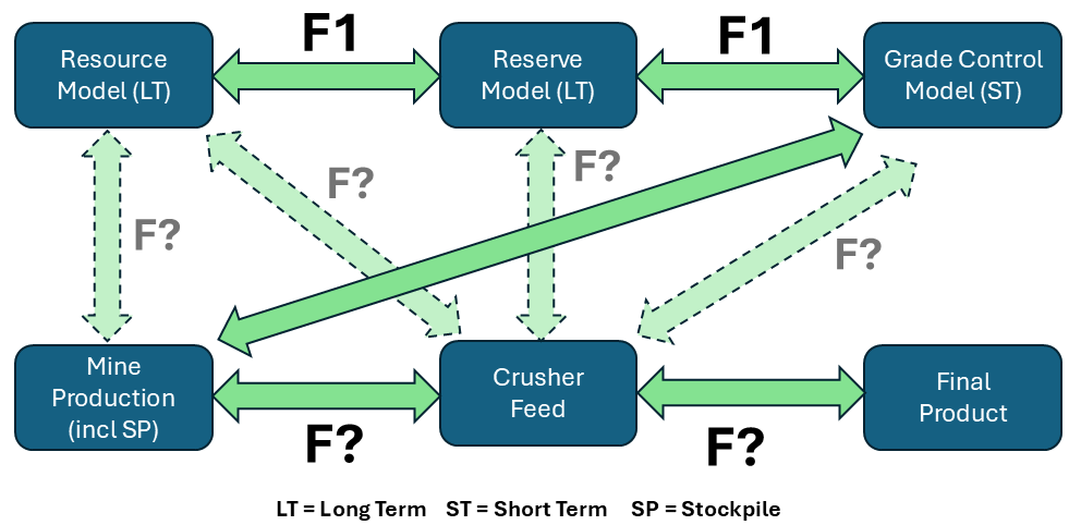 Mine reconciliation requires information such as initial predictions from exploration data and geological models, actual measurement: data from mining sources, such as blast holes, stockpile samples, or mill feed. As well it will need data on the final product being shipped off site. Do the metal quantities balance out throughout the mining operation?
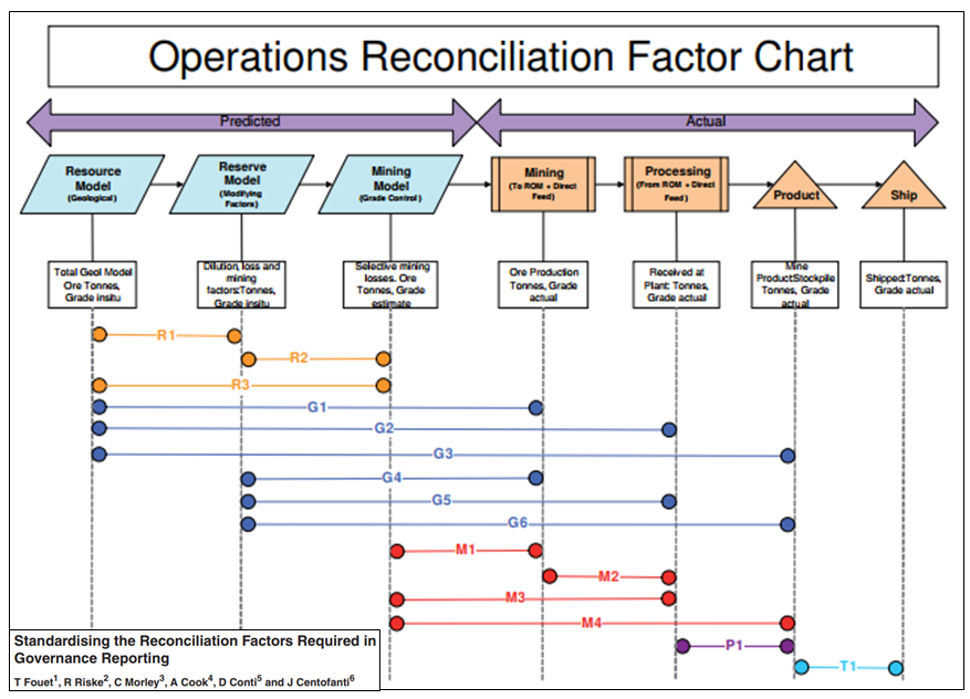
 Each mine site may be unique with respect to; ore sources; terminology; ore types; mining methods; stockpiling philosophy; processing methods; technology availability; and personnel capability. So often the easiest approach for mine reconciliation is based on the Excel spreadsheet. (Reconciliation is generally not an easy undertaking).

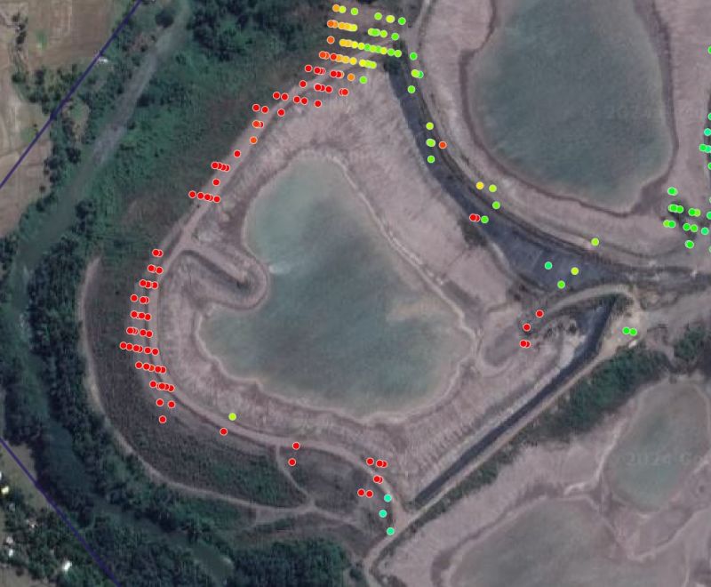 An example of a satellite being used is the Sentinel-1, launched in mid-2015 by the European Space Agency. This satellite information is open-source data. It will have a 6 to 12 day revisit cycle in many locations.
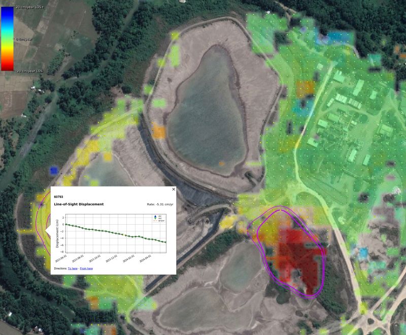 On LinkedIn, one can see numerous posts where independent experts are examining historical InSAR data for recent failures to see whether early movement should have been detected. The results seem to be quite positive in that areas that have failed might have been red-flagged prior to failure.
 A mining site consists of numerous constructed embankments and slopes of all types and heights. Many of these slopes may be creeping and moving all the time – it’s a living beast.